СИСТЕМА ECD > Недостаточная мощность или провал в работе двигателя |
| Malfunction Condition | Main Trouble Area | Related Trouble Area |
|
|
|
| 1.CHECK HARNESS AND CONNECTOR IN ENGINE COMPARTMENT |
Check the wire harness and connector connections of common rail system components.
|
| ||||
| OK | |
| 2.PERFORM CONFIRMATION DRIVING PATTERN |
Enter CHECK MODE (See page Нажмите здесь).
Fully warm up the engine.
Allow the engine to idle for 5 minutes or more.
Drive the vehicle at more than 40 km/h (25 mph) for 1 minute or more (procedure "A").
Decelerate and stop the vehicle (procedure "B").
Repeat procedure "A" and procedure "B" 4 times or more.
Stop the engine and wait for at least 10 seconds (procedure "C").
Repeat procedure "A" and procedure "C" described above to set DTCs relating to the EGR system and throttle valve.
Drive the vehicle at more than 70 km/h (43 mph) for at least 1 minute (to set DTCs relating to the supply pump).
| NEXT | |
| 3.CHECK DTC OUTPUT (RELATING TO ENGINE) |
Connect the intelligent tester to the DLC3.
Turn the ignition switch on (IG) and turn the tester on.
Enter the following menus: Powertrain / Engine and ECT / DTC.
Read pending DTCs.
| Result | Proceed to |
| DTC is not output | A |
| Engine related DTCs | B |
|
| ||||
| A | |
| 4.PERFORM ACTIVE TEST BY INTELLIGENT TESTER (TEST FUEL LEAK) |
Connect the intelligent tester to the DLC3.
Start the engine and turn the tester on.
Enter the following menus: Powertrain / Engine and ECT / Active Test / Test the Fuel Leak.
Visually check the supply pump, injector and fuel line located between the supply pump and common rail for fuel leaks and fuel pressure leaks. Also, perform the same check on the fuel line between the common rail and the injector.
|
| ||||
| OK | |
| 5.CHECK WHITE SMOKE |
Rev up the engine from idling to 3000 rpm several times to check whether white smoke is emitted from the exhaust pipe.
Check that the intake system pipes and hoses are not excessively contaminated with oil.
If white smoke is emitted from the intake system, its pipes and hoses are excessively contaminated with oil. If the presence of white smoke in the exhaust gas is confirmed, there is a high possibility of mechanical problems in the turbocharger or engine.
| Result | Proceed to |
| No problems described above | A |
| White smoke emitted, or intake system pipes and hoses excessively contaminated with oil | B |
|
| ||||
| A | |
| 6.READ VALUE OF DIESEL TURBO PRESSURE SENSOR, MASS AIR FLOW METER AND FUEL PRESSURE SENSOR (MAP AND FUEL PRESS) |
Connect the intelligent tester to the DLC3.
Start the engine, warm it up and turn the tester on.
Enter the following menus: Powertrain / Engine and ECT / Data List.
Select the following menu items in order and read the values.
| Item | Engine Speed *1
| Standard Range | Description |
| MAP *2
| Ignition switch on (IG) (engine stopped) | Same as atmospheric pressure | Intake manifold internal pressure detected by diesel turbo pressure sensor |
| Idling | 85 to 94 kPa (638 to 705 mmHg, 25.10 to 27.76 in.Hg) | ||
| 3000 rpm (no engine load) | 120 to 140 kPa (900 to 1050 mmHg, 35.44 to 41.34 in.Hg) | ||
| 3000 rpm (driving with full throttle acceleration) *5
| 239 to 255 kPa (1793 to 1913 mmHg, 70.58 to 75.30 in.Hg) | ||
| MAF *2, *4
| Ignition switch on (IG) (engine stopped) | Less than 0.55 g/sec. | Intake air volume detected by mass air flow meter |
| Idling | 2.5 to 5.52 g/sec. | ||
| 3000 rpm (no engine load) | 49 to 60 g/sec. | ||
| 3000 rpm (driving with full throttle acceleration) *5
| 124 to 136 g/sec. | ||
| Fuel Press*3
| Idling | 37 to 43 MPa | Common rail internal fuel pressure |
| 2000 rpm (no engine load) | 50 to 56 MPa | ||
| 3000 rpm (no engine load) | 60 to 66 MPa | ||
| 3000 rpm (driving with full throttle acceleration) *5
| 150 to 156 MPa |
| Item | Result | Proceed to |
| MAP, MAF, and Fuel press | Standard range | A |
| MAP and MAF | Outside standard range | B |
| Only MAP | Outside standard range | C |
| Only MAF | Outside standard range | D |
| Only Fuel Press | Outside standard range | E |
|
| ||||
|
| ||||
|
| ||||
|
| ||||
| A | |
| 7.READ VALUE OF INJECTOR (INJECTION FEEDBACK VAL AND INJECTION VOLUME) |
Connect the intelligent tester to the DLC3.
Start the engine, warm it up, and turn the tester on.
Select the following menu items in order and read the values.
| Item | Engine Speed* | Standard Range | Description |
| Injection Feedback Val #1 | Idling | -3.5 to 3.5 mm3
| Value of injector fuel injection volume compensates for differences in combustion condition of cylinders
|
| Injection Feedback Val #2 | Idling | -3.5 to 3.5 mm3
| |
| Injection Feedback Val #3 | Idling | -3.5 to 3.5 mm3
| |
| Injection Feedback Val #4 | Idling | -3.5 to 3.5 mm3
| |
| Injection Volume | Idling | 2.8 to 7.3 mm3
| Fuel injection volume value controlled by ECU
|
| Result | Proceed to |
| Standard range | A |
| Injection Feedback Val #1 to #4 and/or Injection Volume outside standard range | B |
|
| ||||
| A | |
| 8.CHECK INJECTOR COMPENSATION CODE |
Read the injector compensation code (See page Нажмите здесь).
Check the injector compensation code.
|
| ||||
| OK | |
| 9.RESET ECM |
Disconnect the cable from the negative (-) battery terminal for at least 2 minutes.
Reconnect the cable to the negative (-) battery terminal.
Check whether the malfunction has been successfully repaired by performing a driving test using the freeze frame data recorded at the time the malfunction occurred.
|
| ||||
| OK | ||
| ||
| 10.BLEED AIR FROM FUEL SYSTEM |
To bleed air from the priming pump, pump the priming pump until it becomes hard and cannot be pumped any more.
| NEXT | |
| 11.CONFIRM WHETHER LACK OF POWER HAS BEEN SUCCESSFULLY REPAIRED |
Check whether the lack of power has been successfully repaired by performing a driving test. Use the freeze frame data recorded at the time the malfunction occurred.
|
| ||||
| OK | ||
| ||
| 12.INSPECT GLOW PLUG ASSEMBLY |
 |
Disconnect the glow plug wire.
Measure the resistance according to the value(s) in the table below.
| Tester Connection | Condition | Specified Condition |
| Glow plug terminal - Body ground | 20°C (68°F) | Approximately 0.95 Ω |
Reconnect the glow plug wire.
|
| ||||
| OK | |
| 13.CHECK INTAKE SYSTEM |
Check for air leakage and blockage between the air cleaner and turbocharger.
Check for air leakage and blockage between the turbocharger and intake manifold.
| NEXT | ||
| ||
| 14.IDENTIFY MALFUNCTIONING CYLINDER INJECTOR |
Follow the instructions in the table below according to the check result of the intelligent tester.
| Item | Engine Speed* | Reference Value |
| Injection Feedback Val #1 to #4 | Idling | -3.5 to 3.5 mm3
|
| Injection Volume | Idling | 2.8 to 7.3 mm3
|
| Injection Volume | Injection Volume | ||
| Injection Feedback Val #1 to #4 | Less than 2.8 mm3
| Between 2.8 and 7.3 mm3 (Normal) | More than 7.3 mm3
|
| 3.5 mm3 or more, -3.5 mm3 or less | A | B | B |
| Between -3.5 and 3.5 mm3
| - | Normal | C* |
| Proceed to | Inspection Area | Descriptions |
| A | Inspect and repair cylinder injector with revised injection volume of less than -3.5 mm3:
| Abnormal value cylinder injector injects excessively large quantity of fuel |
| B | Identify malfunctioning cylinders by conducting power balance inspection:
| Abnormal value cylinder injector injects excessively small quantity of fuel:
|
| C | Inspect and repair all cylinder injectors: Clean all cylinder injectors, inspect, and repair them | All cylinder injectors inject excessively small quantity of fuel: Fuel injection volume too low due to all cylinder injector nozzles being blocked by deposits |
|
| ||||
|
| ||||
| A | |
| 15.PERFORM ACTIVE TEST BY INTELLIGENT TESTER (INJECTOR CUT FOR IDENTIFYING MALFUNCTIONING CYLINDER) |
Connect the intelligent tester to the DLC3.
Start the engine and turn the tester on.
Enter the following menus: Powertrain / Engine and ECT / Active Test / Control the Cylinder #1, #2, #3, and #4 Fuel Cut.
Check the four cylinders in sequence to identify any faulty cylinders by performing the power balance inspection.
| NEXT | ||
| ||
| 16.PERFORM ACTIVE TEST BY INTELLIGENT TESTER (INJECTOR CUT FOR IDENTIFYING MALFUNCTIONING CYLINDER) |
Connect the intelligent tester to the DLC3.
Start the engine and turn the tester on.
Enter the following menus: Powertrain / Engine and ECT / Active Test / Control the Cylinder #1, #2, #3, and #4 Fuel Cut.
Check the four cylinders in sequence to identify any faulty cylinders by performing the power balance inspection.
| NEXT | |
| 17.CHECK CYLINDER COMPRESSION PRESSURE |
Check the cylinder compression pressure (See page Нажмите здесь).
|
| ||||
| OK | |
| 18.CHECK MALFUNCTIONING CYLINDER'S INJECTOR FOR DEPOSITS |
Check the injector for any deposits.
| Result | Proceed to |
| Injector condition: Deposits | A |
| Injector condition: No deposits | B |
|
| ||||
| A | |
| 19.CLEAN INJECTOR |
Wipe away the deposits from the tips of the injectors.
| NEXT | |
| 20.READ VALUE OF INJECTOR (INJECTION FEEDBACK VAL AND INJECTION VOLUME) |
Reinstall the injector to the cylinder head.
Connect the intelligent tester to the DLC3.
Turn the ignition switch on (IG) and turn the tester on.
Start the engine and warm it up.
Enter the following menus: Powertrain / Engine and ECT / Data List.
Select the following menu items in order and read the values.
| Item | Engine Speed* | Reference Value |
| Injection Feedback Val #1 to #4 | Idling | -3.5 to 3.5 mm3
|
| Injection Volume | Idling | 2.8 to 7.3 mm3
|
|
| ||||
| OK | ||
| ||
| 21.CHECK INJECTORS FOR DEPOSITS (EXCEPT FUEL ADDITION INJECTOR) |
Check the injector for any deposits.
| Result | Proceed to |
| Injector condition: Deposits | A |
| Injector condition: No deposits | B |
|
| ||||
| A | |
| 22.CLEAN INJECTOR |
Wipe away the deposits from the tips of the injectors.
| NEXT | |
| 23.READ VALUE OF INJECTOR (INJECTION FEEDBACK VAL AND INJECTION VOLUME) |
Reinstall the injector to the cylinder head.
Connect the intelligent tester to the DLC3.
Turn the ignition switch on (IG) and turn the tester on.
Start the engine and warm it up.
Enter the following menus: Powertrain / Engine and ECT / Data List.
Select the following menu items in order and read the values.
| Item | Engine Speed* | Reference Value |
| Injection Feedback Val #1 to #4 | Idling | -3.5 to 3.5 mm3
|
| Injection Volume #1 to #4 | Idling | 2.8 to 7.3 mm3
|
|
| ||||
| OK | ||
| ||
| 24.CHECK EGR VALVE ASSEMBLY |
Check the EGR valve assembly (See page Нажмите здесь).
|
| ||||
| OK | |
| 25.INSPECT DIESEL THROTTLE BODY ASSEMBLY |
Connect the intelligent tester to the DLC3.
Turn the ignition switch on (IG) and turn the tester on.
Enter the following menus: Powertrain / Engine and ECT / Diesel Throttle Angle.
Read the value.
|
| ||||
| OK | |
| 26.CHECK INTAKE SYSTEM |
Check for air leakage and blockage between the air cleaner and turbocharger.
Check for air leakage and blockage between the turbocharger and intake manifold.
|
| ||||
| OK | |
| 27.CHECK TURBOCHARGER SUB-ASSEMBLY (MECHANICAL PROBLEM) |
Disconnect the air cleaner hose.
Use a mirror to visually check the turbocharger for any mechanical problems.
When the engine is cold, check that the impeller of the turbocharger rotates smoothly, and perform a contact check to confirm if it is damaged.
Reconnect the air cleaner hose.
|
| ||||
| OK | |
| 28.CHECK VACUUM HOSE (TURBOCHARGER - VRV, VRV - VACUUM PUMP) |
Check that the vacuum hoses are installed correctly.
Check the vacuum hoses for any cracks and damage.
Check the vacuum hoses for air leaks and any blockage.
|
| ||||
| OK | |
| 29.CHECK VRV FOR TURBOCHARGER CONTROL |
Check the VRV (See page Нажмите здесь).
|
| ||||
| OK | |
| 30.INSPECT TURBOCHARGER ACTUATOR |
Inspect the actuator.
|
| ||||
| OK | |
| 31.CONFIRM WHETHER MALFUNCTION HAS BEEN SUCCESSFULLY REPAIRED |
Connect the intelligent tester to the DLC3.
Start the engine, warm it up and turn the tester on.
Enter the following menus: Powertrain / Engine and ECT / Data List.
Select the following menu items in order and read the values.
| Item | Engine Speed *1
| Standard Range | Description |
| MAP *2
| Ignition switch on (IG) (engine stopped) | Same as atmospheric pressure | Intake manifold internal pressure detected by diesel turbo pressure sensor |
| Idling | 85 to 94 kPa (638 to 705 mmHg, 25.10 to 27.76 in.Hg) | ||
| 3000 rpm (no engine load) | 120 to 140 kPa (900 to 1050 mmHg, 35.44 to 41.34 in.Hg) | ||
| 3000 rpm (driving with full throttle acceleration) *5
| 239 to 255 kPa (1793 to 1913 mmHg, 70.58 to 75.30 in.Hg) | ||
| MAF *2, *4
| Ignition switch on (IG) (engine stopped) | Less than 0.55 g/sec. | Intake air volume detected by mass air flow meter |
| Idling | 2.5 to 5.52 g/sec. | ||
| 3000 rpm (no engine load) | 49 to 60 g/sec. | ||
| 3000 rpm (driving with full throttle acceleration) *5
| 124 to 136 g/sec. | ||
| Fuel Press*3
| Idling | 37 to 43 MPa | Common rail internal fuel pressure |
| 2000 rpm (no engine load) | 50 to 56 MPa | ||
| 3000 rpm (no engine load) | 60 to 66 MPa | ||
| 3000 rpm (driving with full throttle acceleration) *5
| 150 to 156 MPa |
|
| ||||
| OK | ||
| ||
| 32.CHECK AND REPLACE FUEL FILTER ASSEMBLY |
| NEXT | |
| 33.CONFIRM WHETHER MALFUNCTION HAS BEEN SUCCESSFULLY REPAIRED |
Connect the intelligent tester to the DLC3.
Start the engine and warm it up, and turn the tester on.
Enter the following menus: Powertrain / Engine and ECT / Data List.
Select the following menu item and read the values.
| Item | Engine Speed* | Reference Value |
| Fuel Press | Idling | 37 to 43 MPa |
| Fuel Press | 2000 rpm (no engine load) | 50 to 56 MPa |
| Fuel Press | 3000 rpm (no engine load) | 60 to 66 MPa |
|
| ||||
| OK | ||
| ||
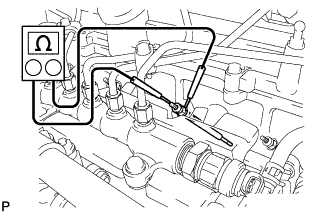
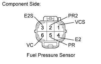
| 34.INSPECT COMMON RAIL ASSEMBLY (FUEL PRESSURE SENSOR) |
 |
Disconnect the fuel pressure sensor connector.
Measure the resistance according to the value(s) in the table below.
| Tester Connection | Condition | Specified Condition |
| 5 (PR) - 4 (E2) | Always | 16.4 kΩ or less |
| 2 (PR2) - 3 (E2S) | Always | 16.4 kΩ or less |
| 5 (PR) - 6 (VC) | Always | 3 kΩ or less |
| 2 (PR2) - 1 (VCS) | Always | 3 kΩ or less |
Reconnect the fuel pressure sensor connector.
|
| ||||
| OK | |
| 35.INSPECT SUPPLY PUMP ASSEMBLY |
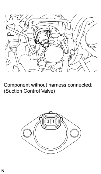 |
Disconnect the suction control valve connector.
Measure the resistance according to the value(s) in the table below.
| Tester Connection | Condition | Specified Condition |
| 1 - 2 | 20°C (68°F) | 1.9 to 2.3 Ω |
Reconnect the suction control valve connector.
|
| ||||
| OK | ||
| ||
