СИСТЕМА ECD > ОПИСАНИЕ СИСТЕМЫ |
| ENGINE CONTROL SYSTEM |
| TOYOTA D-CAT DESCRIPTION |
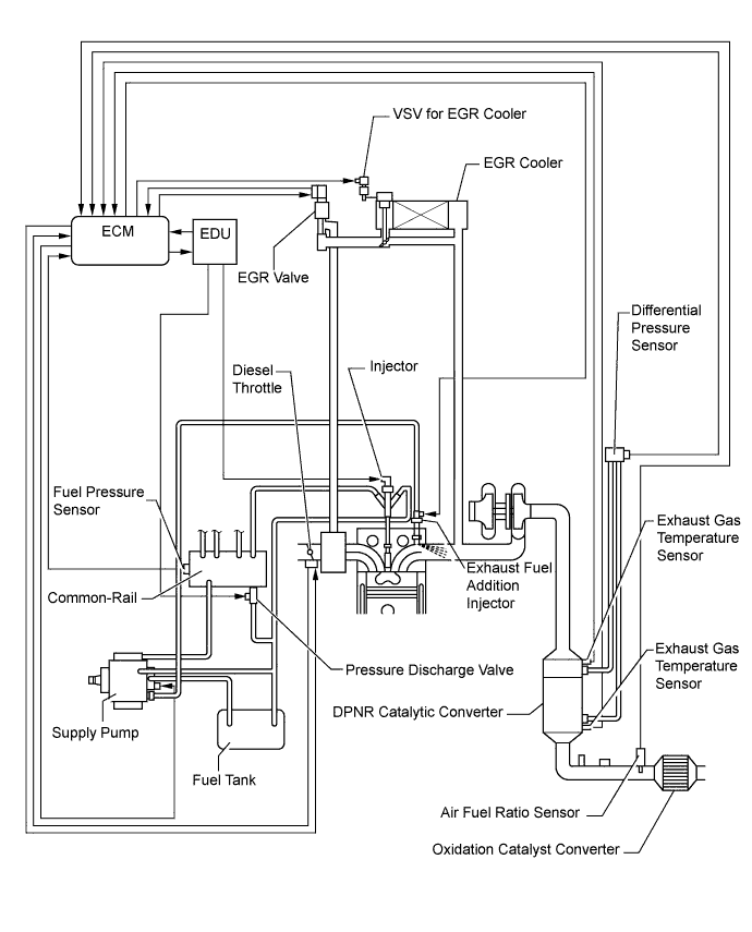
Diesel Clean Advanced Technology (TOYOTA D-CAT) comprehensively regulates engine control (consists of a catalytic system and a fuel injection system) that purifies both particulate matter (PM) and nitrogen oxides (NOx) discharged by diesel engines. The catalytic system purifies hydrocarbons (HC) and carbon monoxides (CO), and reduces PM and NOx with a catalytic converter with the Diesel Particulate-NOx Reduction system (DPNR). The fuel injection system adds fuel into the exhaust port using the exhaust fuel addition injector to produce a RICH state for NOx reduction and maintain a proper catalyst temperature for DPNR catalyst regeneration.
TOYOTA D-CAT components:
| Component | Description |
| DPNR catalytic converter | Reduces HC, CO, PM and NOx. |
| Exhaust fuel addition injector | Adds fuel into the exhaust port in order to produce RICH air-fuel ratio for NOx reduction. Also, raises catalyst temperature for DPNR catalyst regeneration. |
| Exhaust gas temperature sensor | Used for estimating DPNR catalytic converter temperature and adjusting fuel addition by ECM while DPNR catalyst regeneration is performed. Also, detects DPNR catalytic converter temperature to prevent the catalytic converter temperature from rising too high. |
| Differential pressure sensor | Detects the volume of PM deposits and incorrect vacuum hose arrangement on the DPNR catalytic converter. |
| Air fuel ratio sensor | Used for controlling air fuel ratio. By controlling the air fuel ratio, combustion control for low temperature combustion and DPNR catalyst regeneration are properly regulated. |
Diagnostics Trouble Codes (DTCs) table for TOYOTA D-CAT:
| Trouble Area | Malfunction | DTC No. |
| DPNR catalytic converter | Deteriorated or clogged | P2002, P1601, P1386* |
| Exhaust fuel addition injector | Stuck open | P1386 |
| Stuck closed | P1386, P2002* | |
| Low fuel addition volume | P1386, P2002* | |
| Open in exhaust fuel addition injector circuit | P1386, P2047, P2002* | |
| Short in exhaust fuel addition injector circuit | P1386, P2047 | |
| Open or short in exhaust fuel addition injector | P1386, P2047, P2002* | |
| Exhaust gas temperature sensor | Open in exhaust gas temperature sensor circuit | P0544, P0545, P0546, P1386, P2031, P2032, P2033 |
| Short in exhaust gas temperature sensor circuit | P0544, P0545, P0546, P1386*, P2002*, P2031, P2032, P2033 | |
| Exhaust gas temperature sensor | P0544, P0545, P0546, P1386*, P2031, P2032, P2033 | |
| Differential pressure sensor | Open in differential pressure sensor circuit | P1425, P1427, P1428, P2002* |
| Short in differential pressure sensor circuit | P1425, P1427, P1428, P2002* | |
| Differential pressure sensor | P1425, P1427, P1428, P2002* | |
| Differential pressure sensor clogged | P1426, P2002* | |
| Incorrect vacuum hose arrangement of the differential pressure sensor | P1426, P2002* | |
| Air fuel ratio sensor | Open or short in air fuel ratio sensor or heater circuit | P0031, P0032, P1386*, P2238, P2239, P2252, P2253 |
| Air fuel ratio sensor | P0031, P0032, P1386*, P2238, P2239, P2252, P2253 | |
| Exhaust gas leaks | Exhaust gas leaks | P1386*, P2002* |
| Fuel leaks | Fuel leaks in fuel addition injector | P1386* |
| Supply pump | Correct fuel pressure cannot be fed to the exhaust fuel addition injector | P1386* |
Diagnostics trouble code description for TOYOTA D-CAT:
| DTC No. | Description |
| P0031 | Open or short in air fuel ratio sensor heater control circuit (Low output) |
| P0032 | Open or short in air fuel ratio sensor heater control circuit (High output) |
| P0544 | Open or short in exhaust gas temperature sensor circuit (Upstream) |
| P0545 | Open or short in exhaust gas temperature sensor circuit (Upstream) (Low output) |
| P0546 | Open or short in exhaust gas temperature sensor circuit (Upstream) (High output) |
| P1386 | DPNR fuel addition system malfunction |
| P1425 | Open or short in differential pressure sensor circuit |
| P1426 | Differential pressure sensor is clogged or has incorrect vacuum hose arrangement |
| P1427 | Open or short in differential pressure sensor circuit (Low output) |
| P1428 | Open or short in differential pressure sensor circuit (High output) |
| P2002 | DPNR catalytic converter malfunction |
| P2031 | Open or short in exhaust gas temperature sensor circuit (Downstream) |
| P2032 | Open or short in exhaust gas temperature sensor circuit (Downstream) (Low output) |
| P2033 | Open or short in exhaust gas temperature sensor circuit (Downstream) (High output) |
| P2047 | Open in exhaust fuel addition injector circuit |
| P2048 | Open in exhaust fuel addition injector circuit |
| P2049 | Open in exhaust fuel addition injector circuit |
| P2238 | Open or short in air fuel ratio sensor circuit (Low output) |
| P2239 | Open or short in air fuel ratio sensor circuit (High output) |
| P2252 | Open or short in air fuel ratio sensor circuit (Low output) |
| P2253 | Open or short in air fuel ratio sensor circuit (High output) |
| COMMON RAIL SYSTEM DESCRIPTION |
Common rail system:
The common rail system uses high-pressure fuel for improved fuel economy. This system also provides robust engine power, while suppressing engine vibration and noise.
This system stores fuel in the common rail, which has been pressurized and supplied by the supply pump. By storing fuel at high-pressure, the common rail system can provide fuel at stable fuel injection pressures, regardless of engine speed or engine load.
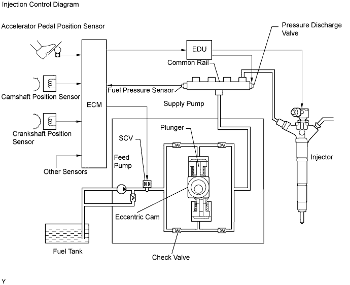
The ECM, using the EDU, provides an electric current to the piezo actuator in each injector to regulate the fuel injection timing and volume. The ECM also monitors the internal fuel pressure of the common rail using the fuel pressure sensor. The ECM causes the supply pump to supply the fuel necessary to obtain the target fuel pressure.
In addition, this system uses a piezo actuator inside each injector to open and close the fuel passages. Therefore, both fuel injection time and fuel injection volume can be precisely regulated by the ECM.
The common rail system allows a two stage fuel injection process. In order to soften combustion shock, this system performs "pilot-injection" prior to the main fuel injection. This helps to reduce engine vibration and noise.

Common rail system components:
| Component | Description |
| Common rail | Stores high-pressure fuel produced by supply pump |
| Supply pump | Operated by crankshaft Supplies high-pressure fuel to common rail |
| Injector | Injects fuel to combustion chamber based on signals from ECM |
| Fuel pressure sensor | Monitors internal fuel pressure of common rail and sends signals to ECM |
| Pressure Discharge Valve | Based on signals from the ECM, opens valve when sudden deceleration has occurred, or when the ignition switch is off to prevent the fuel pressure from becoming too high |
| Suction control valve | Based on signals from ECM, adjusts fuel volume supplied to common rail and regulates internal fuel pressure |
| Check valve | Keeps pressure that discharges from injector |
Diagnostic trouble codes (DTCs) table for the common rail system
| Trouble Area | Malfunction | DTC No. |
| Injector | Open or short in injector circuit | P0200, P1238, P0093* |
| Stuck open | P0093, P1238 | |
| Stuck closed | P1238 | |
| Fuel pressure sensor | Open or short in fuel pressure sensor circuit or pressure sensor output fixed | P0087, P0190, P0191, P0192, P0193 |
| Pressure discharge valve | Open or short in pressure discharge valve circuit | P1271, P1272, P0088*, P0093*, P1229* |
| Stuck open | P0093 | |
| Stuck closed | P1272, P0088* | |
| Suction control valve | Open or short in suction control valve circuit | P0627, P1229, P0088* |
| Stuck open | P1229, P0088* | |
| EDU | Faulty EDU | P0093*, P0200*, P1238*, P1271*, P1272* |
| Common rail system (Fuel system) | Fuel leaks in high-pressure area | P0093 |
Diagnostic trouble code description for the common rail system:
| DTC No. | Description |
| P0087 | Fuel pressure sensor output does not change |
| P0088 | Internal fuel pressure too high (200 MPa [2039 kgf/cm2, 29007 psi] or more) |
| P0093 | Fuel leaks in high-pressure areas |
| P0190 | Open or short in fuel pressure sensor circuit (output voltage is too low or too high) |
| P0191 | Fuel pressure sensor faulty |
| P0192 | Open or short in fuel pressure sensor circuit (output voltage is too low) |
| P0193 | Open or short in fuel pressure sensor circuit (output voltage is too high) |
| P0200 | Open or short in EDU or injector circuit |
| P0627 | Open or short in suction control valve circuit |
| P1229 | Fuel over-feed |
| INJECTION CONTROL SYSTEM DESCRIPTION |
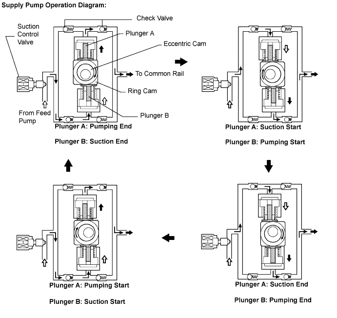
| SUPPLY PUMP OPERATION SYSTEM DESCRIPTION |
| SUCTION CONTROL VALVE OPERATION SYSTEM DESCRIPTION |
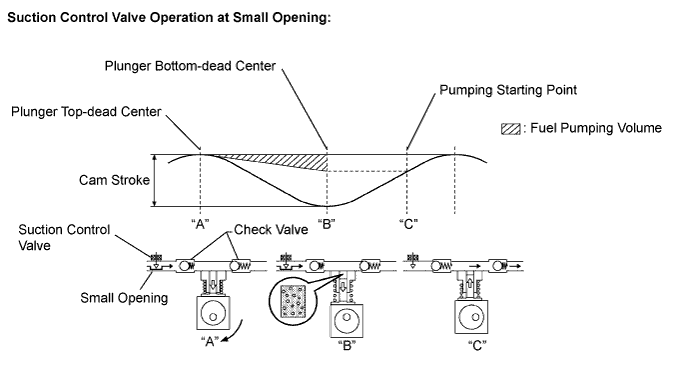
Small opening of the suction control valve:
When the opening of the suction control valve is small, the volume of supplied fuel is small. "A"
The suction volume becomes small due to the narrow path despite the plunger stroke being full. The difference between the geometrical volume and suction volume creates a vacuum. "B"
Pump output will start when the fuel pressure at (A) becomes higher than the common rail pressure (B). "C"
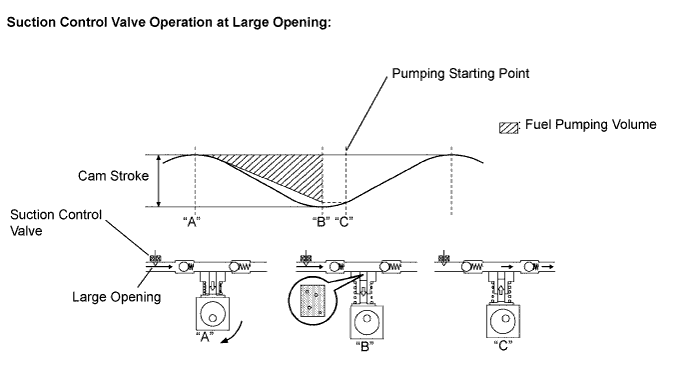
Large opening of the suction control valve:
When the opening of the suction control valve is large, the volume of supplied fuel is increased. "A"
If the plunger stroke is full, the suction volume becomes large because of the wide path. "B"
Pump output will start when the fuel pressure at (A) becomes higher than the common rail pressure (B). "C"