DTC P0500 Vehicle Speed Sensor "A" |
| DTC No. | DTC Detection Condition | Trouble Area |
| P0500 | While vehicle is being driven, no vehicle speed sensor signal to ECM. (2-trip detection logic) |
|
| 1.READ VALUE OF INTELLIGENT TESTER (VEHICLE SPEED) |
Connect the intelligent tester to the DLC3.
Turn the ignition switch on (IG).
Turn the tester on.
Select the following menu items: Powertrain / Engine and ECT / Date List / Vehicle Speed.
Drive the vehicle.
Read the value displayed on the tester.
|
| ||||
| OK | ||
| ||
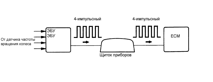
| 2.CHECK COMBINATION METER SYSTEM |
Inspect the circuits that send vehicle speed signals to the combination meter system (See page Нажмите здесь).
During inspection for the combination meter system, if there is an instruction that indicates to go back to inspections for each system, proceed to the next step.
| NEXT | |
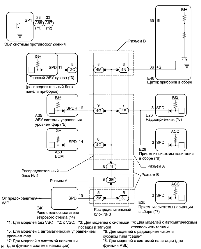
| 3.CHECK HARNESS AND CONNECTOR (ECM - COMBINATION METER) |
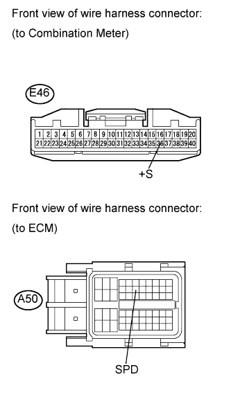 |
Disconnect the ECM connector.
Disconnect the combination meter connector.
Measure the resistance according to the value(s) in the table below.
| Tester Connection | Condition | Specified Condition |
| E46-36 (+S) - A50-14 (SPD) | Always | Below 1 Ω |
Reconnect the ECM connector.
Reconnect the combination meter connector.
|
| ||||
| OK | ||
| ||
| 4.CHECK HARNESS AND CONNECTOR (ECM - NO. 4 JUNCTION BLOCK) |
Disconnect the ECM connector.
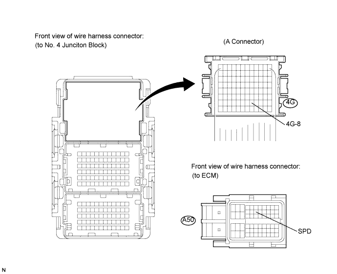
Disconnect the No. 4 junction block connector.
Measure the resistance according to the value(s) in the table below.
| Tester Connection | Condition | Specified Condition |
| 4G-8 - A50-14 (SPD) | Always | Below 1 Ω |
Reconnect the ECM connector.
Reconnect the No. 4 junction block connector.
|
| ||||
| OK | ||
| ||
