ТРОС МЕХАНИЗМА ПЕРЕКЛЮЧЕНИЯ ПЕРЕДАЧ > УСТАНОВКА |
| 1. INSTALL TRANSMISSION CONTROL CABLE ASSEMBLY |
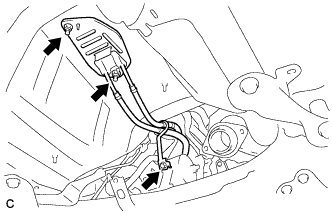 |
Install the transmission control cable assembly with the 2 nuts and bolt.
 |
Install the transmission control cable assembly to the control cable bracket with 2 new clips.
Install the transmission control cable assembly to the transaxle with the 2 clips.
 |
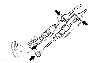
Engage the 2 claws, and install the control cable assembly to the shift lever assembly.
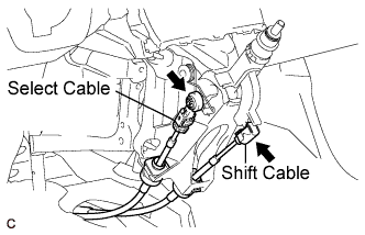 |
Install the control select cable to the shift lever assembly.
Install the control shift cable to the shift lever assembly.
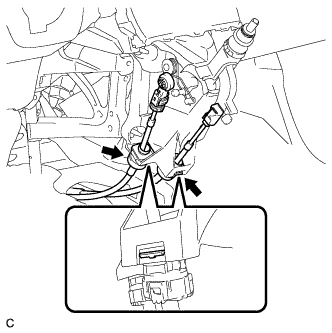
| 2. ADJUST TRANSMISSION CONTROL SELECT CABLE |
Install the transmission control cable assembly to the manual transaxle.
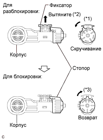 |
Release the lock of the cable length adjustment structure of the select cable.
Twist the stopper.
Pull the lock piece outward from the case to release the lock.
Return the stopper.
Install the transmission control cable assembly to the shift lever assembly.
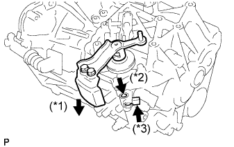 |
Pressing the shift and select lever shaft (*1) and pin (*2), push in pin (*3) and check that the shift and select lever shaft is secured at the 1st-2nd gear selected position (the shaft comes to a stop at the position 8 mm (0.31 in.) below the N position).
Remove the stopper pin, release the lock, and reinsert the stopper pin.
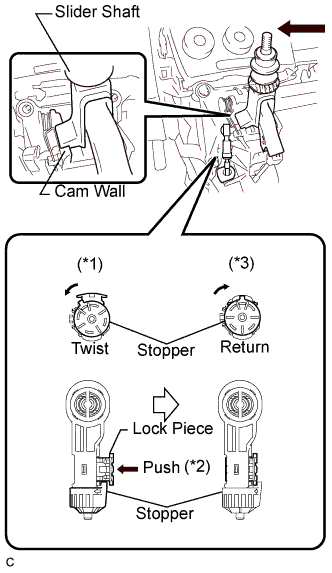 |
Push the slider shaft against the cam wall.
Lock the cable length adjustment structure of the select cable.
Twist the stopper.
Push the lock piece into the case.
Return the stopper to prevent the lock from being released.
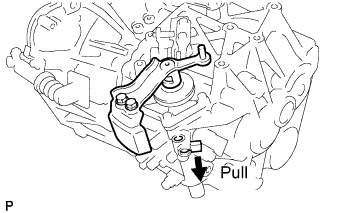 |
Release the pin that fixes the transmission outer lever.
Pull the pin toward the front left side of the vehicle.
| 3. INSTALL LOWER NO. 1 INSTRUMENT PANEL FINISH PANEL |
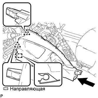 |
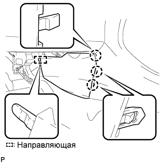
Введите в зацепление 2 захвата и направляющую.
 |
Введите в зацепление 4 захвата и 2 направляющие.
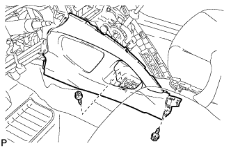 |
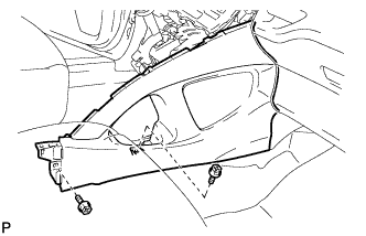
Установите нижнюю отделочную накладку панели приборов № 1 и закрепите ее 2 винтами <E> или <F>.
| 4. INSTALL LOWER NO. 2 INSTRUMENT PANEL FINISH PANEL |
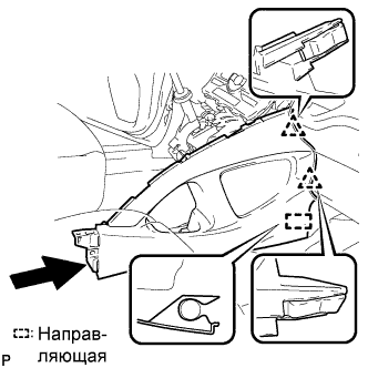 |
Введите в зацепление 2 захвата и направляющую.
 |
Установите нижнюю отделочную накладку панели приборов № 2 и закрепите ее 2 винтами <E> или <F>.
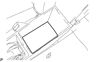
| 5. INSTALL INSTRUMENT PANEL UNDER TRAY |
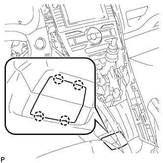 |
Установите нижний лоток панели приборов и закрепите его 4 захватами.
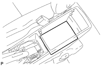
| 6. INSTALL FRONT NO. 1 CONSOLE BOX INSERT |
 |
Введите в зацепление направляющую.
Введите в зацепление 3 захвата и установите переднюю вставку вещевого ящика в облицовке туннеля пола № 1.
| 7. INSTALL FRONT NO. 2 CONSOLE BOX INSERT |
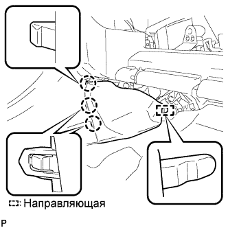 |
Введите в зацепление направляющую.
Введите в зацепление 3 захвата и установите переднюю вставку вещевого ящика в облицовке туннеля пола № 2.
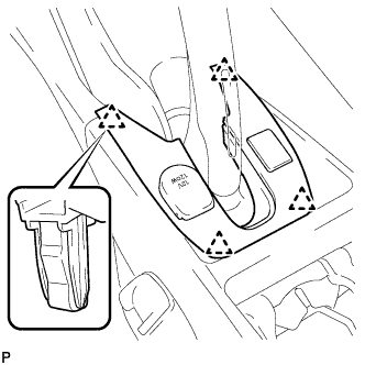
| 8. INSTALL REAR CONSOLE BOX ASSEMBLY (w/o Console Box Lid) |
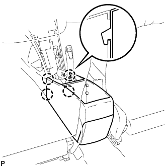 |
Введите в зацепление 4 захвата.
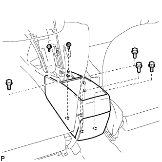 |
Установите вещевой ящик в облицовке туннеля пола и закрепите его 4 болтами и 2 винтами.
| 9. INSTALL REAR CONSOLE BOX ASSEMBLY (w/ Console Box Lid) |
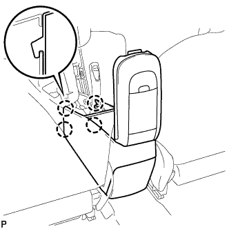 |
Введите в зацепление 4 захвата.
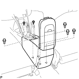 |
Установите вещевой ящик в облицовке туннеля пола и закрепите его 4 болтами и 2 винтами.
| 10. INSTALL CONSOLE BOX CARPET (w/o Console Box Lid) |
 |
Установите коврик вещевого ящика в облицовке туннеля пола.
| 11. INSTALL CONSOLE BOX CARPET (w/ Console Box Lid) |
 |
Установите коврик вещевого ящика в облицовке туннеля пола.
| 12. INSTALL LOWER CENTER INSTRUMENT PANEL FINISH PANEL |
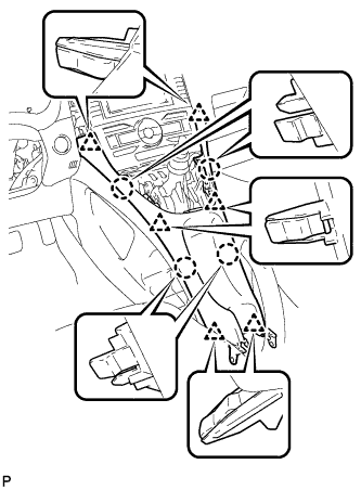 |
Введите в зацепление 4 захвата и 6 фиксаторов и установите центральную нижнюю облицовочную накладку панели приборов.
| 13. INSTALL UPPER CONSOLE PANEL |
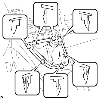 |
Введите в зацепление 7 захватов и установите верхнюю облицовку панели пола.
| 14. INSTALL REAR CONSOLE BOX COVER |
 |
Подсоедините разъем.
Установите крышку вещевого ящика в облицовке туннеля пола и закрепите ее 4 фиксаторами.
| 15. INSTALL SHIFT LEVER KNOB SUB-ASSEMBLY |
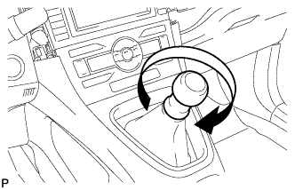 |
Поверните рукоятку рычага переключения передач по часовой стрелке и закрепите ее.
| 16. INSTALL INSTRUMENT PANEL FINISH PANEL END LH |
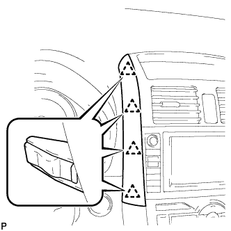 |
Введите в зацепление 4 фиксатора и установите левую отделочную накладку панели приборов.
| 17. INSTALL INSTRUMENT PANEL FINISH PANEL END RH |
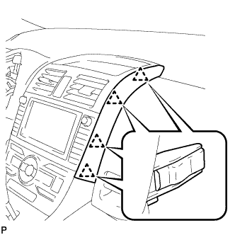 |
Введите в зацепление 4 фиксатора и установите правую отделочную накладку панели приборов.
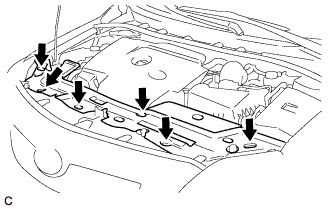
| 18. INSTALL NO. 1 FRONT FLOOR HEAT INSULATOR |
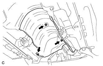 |
Install the No. 1 front floor heat insulator with the 3 nuts.
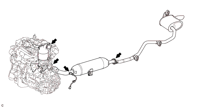
| 19. INSTALL FRONT EXHAUST PIPE ASSEMBLY (for 2AD-FHV) |
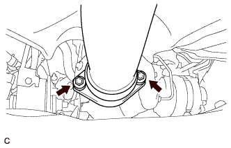 |
Install the exhaust pipe supports, then install the front exhaust pipe assembly with the 2 compression springs and 2 bolts.
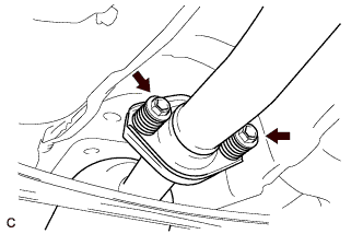 |
Install the 2 compression springs and 2 bolts.
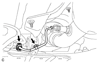 |
Install the air fuel ratio sensor connector and clamp.
| 20. INSTALL AIR CLEANER CASE (for 2AD-FHV) |
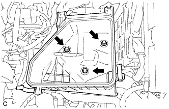 |
Install the 3 bolts and air cleaner case.
| 21. INSTALL AIR CLEANER CAP SUB-ASSEMBLY (for 2AD-FHV) |
Install the air cleaner filter element.
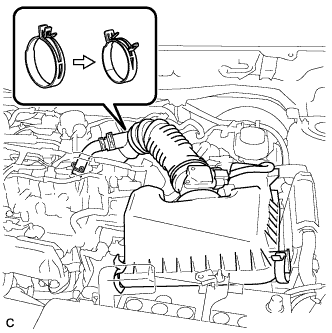 |
Install the air cleaner cap sub-assembly, and connect the 2 clamps and band.
Connect the No. 2 ventilation hose.
Connect the mass air flow meter connector.
| 22. INSTALL BATTERY TRAY |
| 23. INSTALL BATTERY |
| 24. INSTALL BATTERY CLAMP SUB-ASSEMBLY (for 2AD-FHV) |
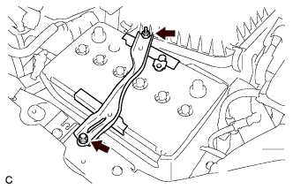 |
Install the battery clamp.
| 25. CONNECT CABLE TO NEGATIVE BATTERY TERMINAL |
| 26. INSTALL UPPER RADIATOR AIR DEFLECTOR |
 |
Install the 6 clips and upper radiator air deflector.
| 27. INSPECT FOR EXHAUST GAS LEAK (for 2AD-FHV) |
Check that there are no exhaust gas leaks from the points (joints of the exhaust pipes and installation points of each sensor) shown in the illustration.