DTC P0810 Clutch Position Control Error |
| DTC No. | DTC Detection Condition | Trouble Area |
| P0810 | The TCM detects the following conditions simultaneously: (1-trip detection logic)
|
|
| 1.CHECK OTHER DTC OUTPUT (IN ADDITION TO DTC P0810) |
Connect the intelligent tester to the DLC3.
Turn the ignition switch on (IG) and turn the tester ON.
Select the following menu items: Powertrain / Multi-Mode M/T / DTC.
Read DTCs.
| Result | Proceed to |
| P0810 | A |
| P0810 and other DTCs | B |
|
| ||||
| A | |
| 2.INSPECT TCM |
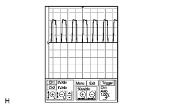 |
Check the clutch actuator motor terminal output using an oscilloscope.
Connect the intelligent tester to the DLC3.
Turn the ignition switch on (IG) and turn the tester ON.
Clear the DTC after saving the recorded freeze frame data.
Turn the ignition switch off within 2 seconds after clearing the DTC.
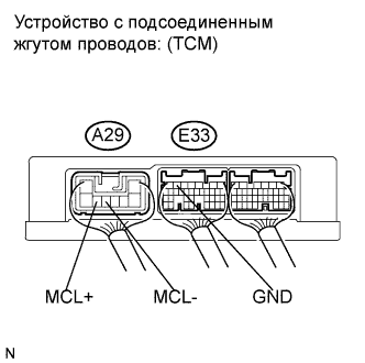 |
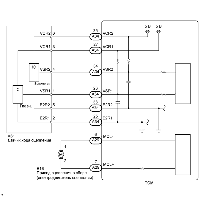
Connect the oscilloscope probes to the TCM terminals.
Check the waveform when the ignition switch is turned on (IG).
| Items | Contents |
| Terminals | A29-6 (MCL-) - E33-6 (GND) A29-7 (MCL+) - E33-6 (GND) |
| Gauge set | 5 V/DIV., 50 μs/DIV. |
| Condition | Soon after ignition switch on (IG) |
|
| ||||
| OK | |
| 3.INSPECT TCM |
 |
Remove the clutch stroke sensor from the clutch actuator assembly.
Connect the clutch stroke sensor connector.
Turn the ignition switch on (IG).
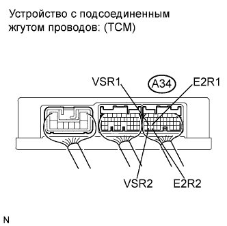
Check the voltage change between the terminals of the TCM connector when moving the sensor arm of the clutch stroke sensor.
| Tester Connection | Switch Condition | Specified Condition |
| A34-26 (VSR1) - A34-25 (E2R1) | Ignition switch on (IG) | Voltage changes in accordance with sensor arm position |
| A34-34 (VSR2) - A34-33 (E2R2) | ↑ | Voltage changes in accordance with sensor arm position |
Reinstall the clutch stroke sensor (See page Нажмите здесь).
Perform initialization and learning (See page Нажмите здесь).
| Result | Proceed to |
| NG | A |
| OK | B |
|
| ||||
| A | |
| 4.INSPECT CLUTCH STROKE SENSOR |
  |
Remove the clutch stroke sensor.
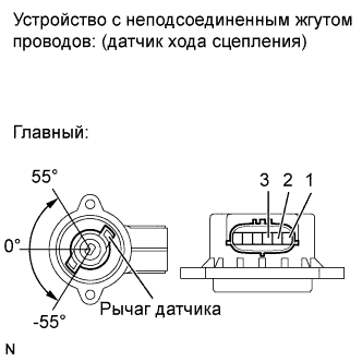
Measure the voltage between the terminals of the clutch stroke sensor connector (main).
Prepare 3 dry cell batteries (1.5 V) and 2 leads for connecting the batteries and the sensor.
Connect the batteries in series.
Connect the positive battery terminal to sensor terminal 3, and the negative battery terminal to sensor terminal 2.
Check the voltage between terminals 1 and 2.
| Sensor Angle | Terminal (1-2) Output Voltage |
| 55° | Approximately 4.05 V |
| 0° | Approximately 2.25 V |
| -55° | Approximately 0.45 V |
| Sensor Angle | Terminal (1-2) Output Voltage |
| 55° | Approximately 4.5 V |
| 0° | Approximately 2.5 V |
| -55° | Approximately 0.5 V |
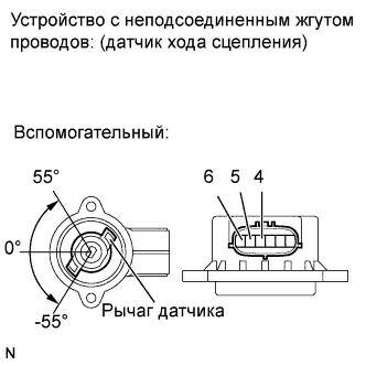
Measure the voltage between the terminals of the clutch stroke sensor connector (sub).
Connect the positive battery terminal to sensor terminal 6, and the negative battery terminal to sensor terminal 5.
Check the voltage between terminals 4 and 5.
| Sensor Angle | Terminal (4-5) Output Voltage |
| 55° | Approximately 4.05 V |
| 0° | Approximately 2.25 V |
| -55° | Approximately 0.45 V |
| Sensor Angle | Terminal (4-5) Output Voltage |
| 55° | Approximately 4.5 V |
| 0° | Approximately 2.5 V |
| -55° | Approximately 0.5 V |
Reinstall the clutch stroke sensor (See page Нажмите здесь).
Perform initialization and learning (See page Нажмите здесь).
|
| ||||
| OK | ||
| ||
| 5.PERFORM ACTIVE TEST USING INTELLIGENT TESTER |
Remove the clutch actuator (See page Нажмите здесь).
Connect the clutch stroke sensor connector and the clutch actuator connector.
Connect the intelligent tester to the DLC3.
Turn the ignition switch on (IG) and the tester ON.
Clear the DTC after saving the recorded freeze frame data.
Turn the ignition switch off within 2 seconds after clearing the DTC.
Turn the ignition switch on (IG).
Select the following menu items: Powertrain / Multi-Mode M/T / Active Test / Target Clutch Control.
Perform the Active Test.
Reinstall the clutch actuator.
Perform initialization and learning (See page Нажмите здесь).
|
| ||||
| OK | |
| 6.CHECK CLUTCH SYSTEM (CLUTCH MECHANICAL OPERATION) |
Remove the transaxle assembly (See page Нажмите здесь).
Check for dirt, wear and defects in the clutch system parts (clutch disc, clutch cover, release bearing and release fork).
|
| ||||
| OK | ||
| ||
