DTC P0400 Exhaust Gas Recirculation Flow |
| DTC No. | DTC Detection Condition | Trouble Area |
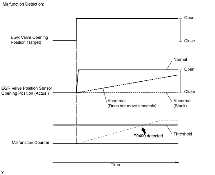
| P0400 | When either condition below is met:
|
|
| 1.CHECK OTHER DTC OUTPUT (IN ADDITION TO DTC P0400) |
Connect the intelligent tester to the DLC3.
Turn the ignition switch on (IG) and turn the tester on.
Enter the following menus: Powertrain / Engine and ECT / DTC.
Read the DTCs.
| Result | Proceed to |
| DTC P0400 is output | A |
| DTC P0400 and P0405 and/or P0406 are output | B |
|
| ||||
| A | |
| 2.READ VALUE OF INTELLIGENT TESTER (EGR POSITION) |
Connect the intelligent tester to the DLC3.
Turn the ignition switch on (IG) and turn the tester on.
Enter the following menus: Powertrain / Engine and ECT / Data List / EGR Position.
Read the value.
| Condition | Result | Proceed to |
| After warming up the engine, quickly accelerate the engine from idling to 3000 rpm by using the accelerator pedal | Constant or changes slowly | A |
| Smooth changes from approximately 0% to approximately 50% | B |
|
| ||||
| A | |
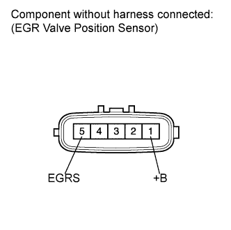
| 3.INSPECT EGR VALVE ASSEMBLY (EGR VALVE POSITION SENSOR RESISTANCE) |
 |
Disconnect the EGR valve position sensor connector.
Measure the resistance according to the value(s) in the table below.
| Tester Connection | Condition | Specified Condition |
| 5 (EGRS) - 1 (+B) | 20°C (68°F) | Approximately 6.5 to 7.5 Ω |
Reconnect the EGR valve position sensor connector.
|
| ||||
| OK | |
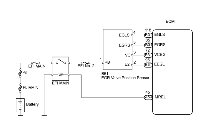
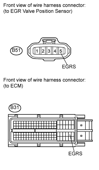
| 4.CHECK HARNESS AND CONNECTOR (EGR VALVE ASSEMBLY - ECM) |
 |
Disconnect the EGR valve position sensor connector.
Disconnect the ECM connector.
Measure the resistance according to the value(s) in the table below.
| Tester Connection | Condition | Specified Condition |
| B51-5 (EGRS) - B31-85 (EGRS) | Always | Below 1 Ω |
| Tester Connection | Condition | Specified Condition |
| B51-5 (EGRS) or B31-85 (EGRS) - Body ground | Always | 10 kΩ or higher |
Reconnect the EGR valve position sensor connector.
Reconnect the ECM connector.
|
| ||||
| OK | |
| 5.INSPECT FUSE (EFI NO. 2 FUSE) |
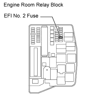 |
Remove the EFI No. 2 fuse from the engine room relay block.
Measure the resistance according to the value(s) in the table below.
| Tester Connection | Condition | Specified Condition |
| EFI No. 2 fuse | Always | Below 1 Ω |
Reinstall the EFI No. 2 fuse.
|
| ||||
| OK | |
| 6.CHECK HARNESS AND CONNECTOR (EGR VALVE ASSEMBLY - EFI MAIN RELAY) |
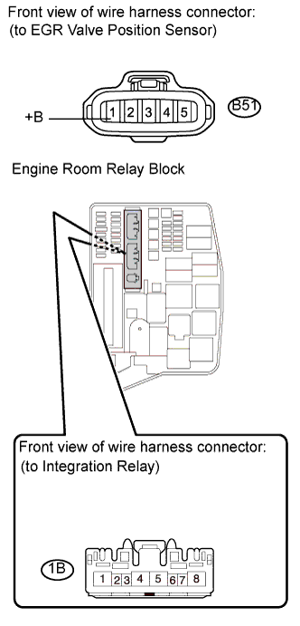 |
Check the wire harness between the EGR valve position sensor and EFI MAIN relay.
Disconnect the EGR valve position sensor connector.
Remove the integration relay from the engine room relay block.
Disconnect the integration relay connector.
Measure the resistance according to the value(s) in the table below.
| Tester Connection | Condition | Specified Condition |
| B51-1 (+B) - 1B-4 | Always | Below 1 Ω |
| Tester Connection | Condition | Specified Condition |
| B51-1 (+B) or 1B-4 - Body ground | Always | 10 kΩ or higher |
Reconnect the EGR valve position sensor connector.
Reconnect the integration relay connector.
Reinstall the integration relay.
|
| ||||
| OK | |
| 7.REPLACE EGR VALVE ASSEMBLY |
Replace the EGR valve position sensor (See page Нажмите здесь).
| NEXT | |
| 8.CHECK WHETHER DTC OUTPUT RECURS |
Connect the intelligent tester to the DLC3.
Turn the ignition switch on (IG) and turn the tester on.
Clear the DTCs (See page Нажмите здесь).
Start the engine and drive the vehicle for approximately 15 minutes.
Enter the following menus: Powertrain / Engine and ECT / DTC.
Read the DTCs.
| Result | Proceed to |
| DTC P0400 is output | A |
| DTC is not output | B |
|
| ||||
| A | ||
| ||
