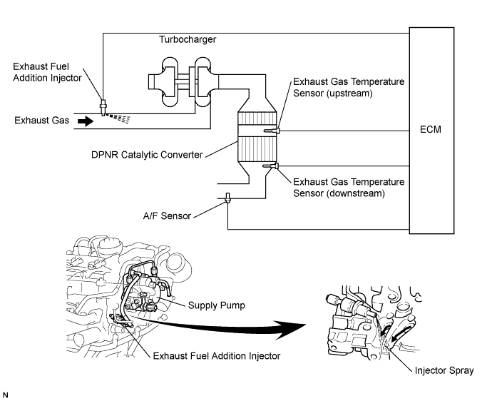
DTC P1386 Injector for Exhaust Fuel Addition |
| DTC No. | DTC Detection Condition | Main Trouble Area | Related Trouble Area |
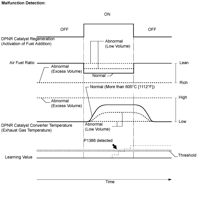
| P1386 | Excess or low fuel addition volume from exhaust fuel addition injector: Air-fuel ratio deviates from a value estimated by ECM while the injector is adding fuel (1-trip detection logic) |
|
|
| Low fuel addition volume from exhaust fuel addition injector: Learning value*3 exceeds standard level (1-trip detection logic) | |||
| Exhaust fuel addition injector nozzle stuck open: Air-fuel ratio becomes RICHER than standard level, or exhaust gas temperature becomes higher than standard level (1-trip detection logic) |
| Fail-Safe Operation | Malfunction Condition | Malfunction Detection Condition | Drive Pattern |
| No fail-safe operation | Low or excess fuel addition volume from the exhaust fuel addition injector | When the exhaust fuel addition injector adds fuel during NOx reduction, if actual air-fuel ratio deviates from a value estimated by the ECM when the exhaust fuel addition injector adds fuel | After warming up the engine, perform DPNR REJU (PM) in the ACTIVE TEST menu using the intelligent tester, and drive at constant vehicle speed within 50 to 100 km/h (31 to 62 mph) for more than 15 minutes |
| Limits engine power to maximum vehicle speed of approximately 80 km/h (50 mph) | Exhaust fuel addition injector is stuck open | DPNR catalytic converter temperature becomes higher than 800°C (1472°F) or air-fuel ratio is less than approximately 12.0: 1 for a couple of seconds | Idling engine for more than 5 minutes*5 |
Limits engine power to maximum vehicle speed of approximately 80 km/h (50 mph)
| Low fuel addition volume from the exhaust fuel addition injector | During DPNR catalyst regeneration, when learning value of 1.99 or more continues for a certain period of time*6 | After warming up the engine, perform DPNR REJU (PM) in the ACTIVE TEST menu using the intelligent tester, and drive at constant vehicle speed within 50 to 100 km/h (31 to 62 mph) for more than 30 minutes |
| 1.CHECK OTHER DTC OUTPUT (IN ADDITION TO DTC P1386) |
Connect the intelligent tester to the DLC3.
Turn the ignition switch on (IG).
Turn the tester on.
Enter the following menu items: Powertrain / Engine and ECT / DTC.
Read the DTCs.
| Result | Proceed to |
| DTC P1386 is output | A |
| DTC P1386 and other DTCs are output | B |
|
| ||||
| A | |
| 2.READ VALUE OF EXHAUST GAS TEMPERATURE |
Connect the intelligent tester to the DLC3.
Turn the ignition switch on (IG). (Do not start the engine.)
Turn the tester on.
Enter the following menu items: Powertrain / Engine and ECT / Data List / Initial Exhaust Temp (In) and Initial Exhaust Temp (Out).
Read the value.
| Result | Proceed to |
| Temperature displayed: OK (Same value as actual exhaust gas temperature) | A |
| Temperature displayed: 1000°C (1832°F) | B |
|
| ||||
| A | |
| 3.PERFORM ENGINE RPM ACCELERATION (WHITE SMOKE AND FUEL SMELL) |
Disconnect the battery cable for 1 minute, and then reconnect the cable.
After the engine starts, promptly accelerate the engine to approximately 3000 rpm with no load 3 times.
Check for white smoke in exhaust gases.
Check for a fuel smell in exhaust gases.
| Result | Proceed to |
| Other than following | A |
| Either white smoke or fuel smells in exhaust gases | B |
|
| ||||
| A | |
| 4.READ VALUE OF AIR FUEL RATIO |
Connect the intelligent tester to the DLC3.
Turn the ignition switch on (IG).
Turn the tester on.
Start the engine.
Enter the following menu items: Powertrain / Engine and ECT / Data List / AFS B1 S1.
Read the air fuel ratio displayed on the tester after idling the engine for 3 minutes.
| Result | Proceed to |
| Air fuel ratio: More than 12 | A |
| Air fuel ratio: Less than 12 | B |
|
| ||||
| A | |
| 5.READ VALUE OF EXHAUST GAS TEMPERATURE |
Connect the intelligent tester to the DLC3.
Turn the ignition switch on (IG).
Turn the tester on.
Start the engine.
Enter the following menu items: Powertrain / Engine and ECT / Data List / Initial Exhaust Temp (In) and Initial Exhaust Temp (Out).
Check that exhaust gas temperature is within the specification below.
| Result | Exhaust Gas Temperature (°C) |
| Idling after warming up engine | Constant at approximately 50 to 700°C (122 to 1292°F) |
|
| ||||
| OK | |
| 6.READ VALUE OF AIR FUEL RATIO |
Connect the intelligent tester to the DLC3.
Turn the ignition switch on (IG).
Turn the tester on.
Start the engine.
Enter the following menu items: Powertrain / Engine and ECT / Data List / AFS B1 S1.
After warming up the engine, check if the air fuel ratio varies when accelerating the engine from idling to 3000 rpm by fully depressing the accelerator pedal 3 times.
| Result | Proceed to |
| Air fuel ratio: Varies | OK |
| Air fuel ratio: Does not vary once | NG |
|
| ||||
| OK | |
| 7.INSPECT EXHAUST FUEL ADDITION INJECTOR ASSEMBLY |
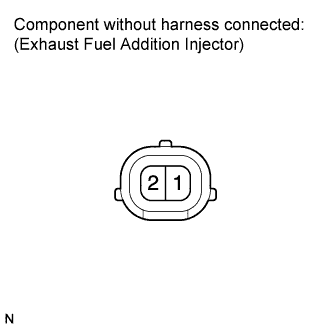 |
Disconnect the exhaust fuel addition injector connector.
Measure the resistance according to the value(s) in the table below.
| Tester Connection | Condition | Specified Condition |
| 1 - 2 | 20°C (68°F) | 7.1 to 7.9 Ω |
Reconnect the exhaust fuel addition injector connector.
|
| ||||
| OK | |
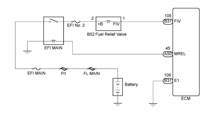
| 8.CHECK FUSE (EFI NO. 2 FUSE) |
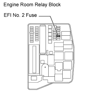 |
Remove the EFI No. 2 fuse from the engine room relay block.
Measure the resistance according to the value(s) in the table below.
| Tester Connection | Condition | Specified Condition |
| EFI No. 2 fuse | Always | Below 1 Ω |
Reinstall the EFI No. 2 fuse.
|
| ||||
| OK | |
| 9.CHECK HARNESS AND CONNECTOR (EXHAUST FUEL ADDITION INJECTOR ASSEMBLY - ECM) |
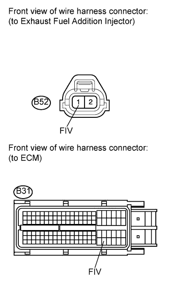 |
Disconnect the exhaust fuel addition injector assembly connector.
Disconnect the ECM connector.
Measure the resistance according to the value(s) in the table below.
| Tester Connection | Condition | Specified Condition |
| B52-1 (FIV) - B31-105 (FIV) | Always | Below 1 Ω |
| Tester Connection | Condition | Specified Condition |
| B52-1 (FIV) or B31-105 (FIV) - Body ground | Always | 10 kΩ or higher |
Reconnect the exhaust fuel addition injector assembly connector.
Reconnect the ECM connector.
|
| ||||
| OK | |
| 10.CHECK HARNESS AND CONNECTOR (EXHAUST FUEL ADDITION INJECTOR ASSEMBLY - EFI MAIN RELAY) |
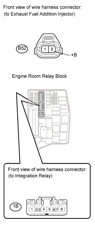 |
Disconnect the exhaust fuel addition injector assembly connector.
Remove the integration relay from the engine room relay block.
Disconnect the integration relay connector.
Measure the resistance according to the value(s) in the table below.
| Tester Connection | Condition | Specified Condition |
| B52-2 (+B) - 1B-4 | Always | Below 1 Ω |
| Tester Connection | Condition | Specified Condition |
| B52-2 (+B) or 1B-4 - Body ground | Always | 10 kΩ or higher |
Reconnect the exhaust fuel addition injector connector.
Reconnect the integration relay connector.
Reinstall the integration relay.
|
| ||||
| OK | |
| 11.INSPECT FOR FUEL LEAK (IN EXHAUST FUEL ADDITION INJECTOR) |
Visually check if there is a fuel leak between the supply pump and exhaust fuel addition injector.
|
| ||||
| OK | |
| 12.READ VALUE OF INJECTION VOLUME (COMPENSATION OF INJECTION VOLUME) |
Connect the intelligent tester to the DLC3.
Turn the ignition switch on (IG).
Turn the tester on.
Start the engine.
Enter the following menu items: Powertrain / Engine and ECT / Data List / Injection Feedback Value.
Read the value.
| Result | Proceed to |
| Compensatory injection volume is more than 3.0 mm3 (0.00018 cu.in.) | A |
| Compensatory injection volume is 3.0 mm3 (0.00018 cu.in.) or less | B |
|
| ||||
| A | |
| 13.CHECK ENGINE COMPONENT PARTS |
Check that there is no abnormality in the main injector, cylinder compression pressure, valve timing, and valve clearance.
Check that there is no leakage or blockage in the air intake, exhaust, and EGR systems.
|
| ||||
| OK | |
| 14.INSPECT EXHAUST FUEL ADDITION INJECTOR (INJECTION VOLUME) |
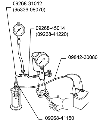 |
Remove the exhaust fuel addition injector.
Attach the exhaust fuel addition injector to a nozzle tester.
Apply a pressure of 0.29 MPa (3.0 kgf/cm2, 42 psi) to the nozzle tester.
Connect SST (wire) to the exhaust fuel addition injector.
Inspect the injector.
| Condition | Result |
| Leave the injector undisturbed for 1 minute with fuel pressurized | No leakage from the injector |
| Apply battery voltage to the injector | Fuel is emitted from the injector |
Reinstall the exhaust fuel addition injector.
|
| ||||
| OK | |
| 15.PERFORM ACTIVE TEST BY INTELLIGENT TESTER (DPNR CATALYST REGENERATION) |
Clear the learning value by removing the negative battery cable for more than 1 minute.
Connect the intelligent tester to the DLC3.
Turn the ignition switch on (IG).
Turn the tester on.
Enter the following menu items: Powertrain / Engine and ECT / Active Test / Activate the DPF Rejuvenate (PM).
After warming up the engine, drive the vehicle at a constant speed between 50 and 100 km/h (31 and 62 mph) (with smooth throttle operations) for more than 15 minutes.
Enter the following menus: "Powertrain / Engine and ECT / Data List / AFS B1 S1, Initial Exhaust Temp (In), Initial Exhaust Temp (Out) and Exhaust Fuel Addition FB".
Check the exhaust gas temperatures (Initial Exhaust Temp (In) and (Out)) and the learning value (Exhaust Fuel Addition FB).
| Result | Proceed to |
| Exhaust gas temperature does not become higher than 600°C (1112°F) | A |
| Exhaust gas temperature becomes higher than 600°C (1112°F), and the learning value remains in the vicinity of 1.0 | B |
|
| ||||
| A | |
| 16.REPLACE EXHAUST FUEL ADDITION INJECTOR ASSEMBLY |
Replace the exhaust fuel addition injector assembly (See page Нажмите здесь).
| NEXT | |
| 17.PERFORM ACTIVE TEST BY INTELLIGENT TESTER (DPNR CATALYST REGENERATION) |
Clear the learning value by removing the negative battery cable for more than 1 minute.
Connect the intelligent tester to the DLC3.
Turn the ignition switch on (IG).
Turn the tester on.
Enter the following menu items: Powertrain / Engine and ECT / Active Test / Activate the DPF Rejuvenate (PM).
After warming up the engine, drive the vehicle at a constant speed between 50 and 100 km/h (31 and 62 mph) (with smooth throttle operations) for more than 15 minutes.
Enter the following menu items: Powertrain / Engine and ECT / Data List / AFS B1 S1, Initial Exhaust Temp (In), Initial Exhaust Temp (Out) and Exhaust Fuel Addition FB.
Check the exhaust gas temperatures (Initial Exhaust Temp (In) and (Out)) and the learning value (Exhaust Fuel Addition FB).
| Result | Proceed to |
| Exhaust gas temperature does not become higher than 600°C (1112°F) | A |
| Exhaust gas temperature becomes higher than 600°C (1112°F), and the learning value remains in the vicinity of 1.0 | B |
|
| ||||
| A | ||
| ||
| 18.INSPECT EXHAUST FUEL ADDITION INJECTOR (INJECTION VOLUME) |
|
Remove the exhaust fuel addition injector.
Attach the exhaust fuel addition injector to a nozzle tester.
Apply a pressure of 0.29 MPa (3.0 kgf/cm2, 42 psi) to the nozzle tester.
Connect SST (Wire) to the exhaust fuel addition injector.
Inspect the injector.
| Condition | Result |
| Leave the injector undisturbed for 1 minute with fuel pressurized | No leakage from the injector |
| Apply battery voltage to the injector | Fuel is emitted from the injector |
Reinstall the exhaust fuel addition injector.
|
| ||||
| OK | ||
| ||
