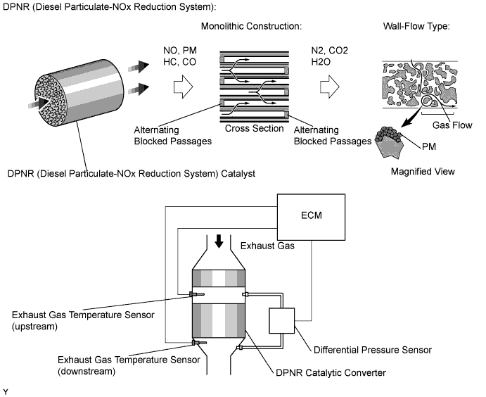
DTC P2002 Particulate Trap Efficiency Below Threshold (Bank1) |
| DTC No. | DTC Detection Condition | Trouble Area |
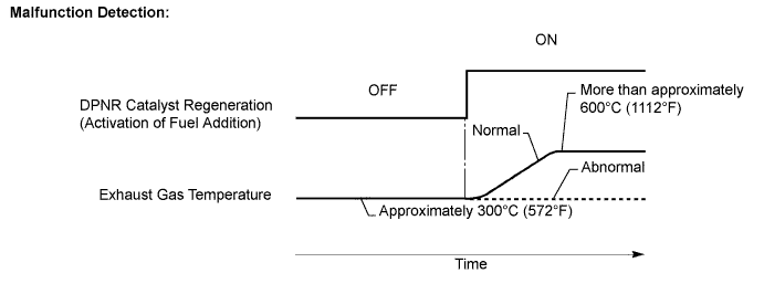
| P2002 | Condition (a), (b) or (c) is met (1-trip detection logic): (a) Differential pressure exceeds a standard level for more than 10 seconds (b) Exhaust gas temperature does not rise during DPNR catalyst regeneration (c) The DPNR catalyst thermal deterioration data exceeds the threshold. |
|
| 1.CHECK CATALYST RECORD OF DPNR THERMAL DETERIORATION |
Connect the intelligent tester to the DLC3.
Turn the ignition switch on (IG).
Turn the tester on.
Enter the following menu items: Powertrain / Engine and ECT / Data List / DPF Catalyst Deteriorate.
|
| ||||
| OK | |
| 2.CHECK OTHER DTC OUTPUT (IN ADDITION TO DTC 2002) |
Connect the intelligent tester to the DLC3.
Turn the ignition switch on (IG).
Turn the tester on.
Enter the following menu items: Powertrain / Engine and ECT / DTC.
Read the DTCs.
| Result | Proceed to |
| DTC P2002 is output | A |
| DTC P2002 and other DTCs are output | B |
|
| ||||
| A | |
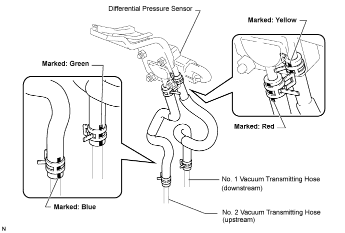
| 3.CHECK BLOCKAGE OF VACUUM HOSE AND TRANSMITTING PIPE |
Disconnect the vacuum hose (both upstream and downstream) on the differential pressure sensor side.
Start the engine.
Check for exhaust gas pulsations from both vacuum hoses while the engine is idling.
|
| ||||
| OK | |
| 4.INSPECT FOR EXHAUST GAS LEAK |
Check that there is no exhaust gas leak in the exhaust system components and differential pressure sensor vacuum hoses.
|
| ||||
| OK | |
| 5.READ VALUE OF DIFFERENTIAL PRESSURE |
Connect the intelligent tester to the DLC3.
Turn the ignition switch on (IG).
Turn the tester on.
Start the engine.
Enter the following menu items: Powertrain / Engine and ECT / Data List / Differential Pressure FB and MAF.
Check the differential pressure.
| Engine Speed (Vehicle is stop) | Differential Pressure (kPa) | Proceed to |
| 3000 rpm (No engine load) | Less than mass air flow rate x 0.31 | A |
| 3000 rpm (No engine load) | More than mass air flow rate x 0.31 | B |
| Condition | Differential Pressure Output | Sensor Condition |
| Ignition switch on (IG) | Approximately 0 kPa | Normal |
| Always | 3 kPa | Open or short circuit |
| 3000 rpm (No engine load) | Negative output | Incorrect arrangement of hose piping |
|
| ||||
| A | |
| 6.READ VALUE OF EXHAUST GAS TEMPERATURE |
Connect the intelligent tester to the DLC3.
Turn the ignition switch on (IG).
Turn the tester on.
Start the engine.
Enter the following menu items: Powertrain / Engine and ECT / Data List / Initial Exhaust Temperature (In) and Initial Exhaust Temperature (Out).
Check that exhaust gas temperature is within the specification below.
| Condition | Exhaust Gas Temperature (°C) |
| Idling after warming up engine | Constant at approximately 50 to 700 (122 to 1292°F) *1 |
|
| ||||
| OK | |
| 7.PERFORM ACTIVE TEST BY EXHAUST FUEL ADDITION INJECTOR (ACTIVE THE DPNR REJUVENATE (PM)) |
Connect the intelligent tester to the DLC3.
Turn the ignition switch on (IG).
Turn the tester on.
Drive the vehicle.
Enter the following menu items: Powertrain / Engine and ECT / Active Test / Active the DPF Rejuvenate (PM).
Check that exhaust gas temperature increases after switching the DPF Rejuvenate (PM) from OFF to ON.
|
| ||||
| OK | ||
| ||
| 8.READ VALUE OF INJECTOR (INJECTION FEEDBACK VAL AND INJECTION VOLUME) |
Select the following menu items in order and read the values.
| Item | Engine Speed* | Standard Range | Description |
| Injection Feedback Val #1 | Idling | -3.5 to 3.5 mm3
| Value of injector fuel injection volume compensates for differences in combustion condition of cylinders
|
| Injection Feedback Val #2 | Idling | -3.5 to 3.5 mm3
| |
| Injection Feedback Val #3 | Idling | -3.5 to 3.5 mm3
| |
| Injection Feedback Val #4 | Idling | -3.5 to 3.5 mm3
| |
| Injection Volume | Idling | 2.8 to 7.3 mm3
| Fuel injection volume value controlled by ECU
|
|
| ||||
| OK | |
| 9.CHECK EXHAUST FUEL ADDITION INJECTOR (INJECTION VOLUME) |
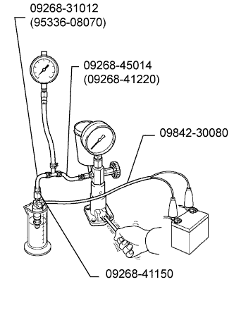 |
Remove the exhaust fuel addition injector.
Attach the exhaust fuel addition injector to a nozzle tester.
Apply a pressure of 0.29 MPa (3.0 kgf/cm2, 42 psi) to the nozzle tester.
Connect SST (wire) to the exhaust fuel addition injector.
Inspect the injector.
| Condition | Result |
| Leave the injector undisturbed for 1 minute with fuel pressurized | No leakage from the injector |
| Apply battery voltage to the injector | Fuel is emitted from the injector |
Reinstall the exhaust fuel addition injector.
|
| ||||
| OK | |
| 10.CHECK TURBOCHARGER ACTUATOR |
Inspect the actuator.
|
| ||||
| OK | |
| 11.READ VALUE OF MASS AIR FLOW METER |
Connect the intelligent tester to the DLC3.
Start the engine and warm it up.
Turn the tester on.
Enter the following menu items: Powertrain / Engine and ECT / Data List.
Select the following menu items in order and read the values.
| Item | Engine Speed *1 | Standard Range | Description |
| MAF *2, *3 | Ignition switch on (IG) (engine stopped) | Less than 0.55g/sec. | Intake air volume detected by mass air flow meter |
| Idling | 2.5 to 5.52 g/sec. | ||
| 3000 rpm (no engine load) | 49 to 60 g/sec. | ||
| 3000 rpm (driving with full throttle acceleration) *4 | 124 to 136 g/sec. |
|
| ||||
| OK | ||
| ||
