DTC P2047 Reductant Injector Circuit / Open (Bank 1 Unit 1) |
DTC P2048 Short to GND in Reductant Injector Circuit (Bank 1) |
DTC P2049 Short to B+ in Reductant Injector Circuit (Bank 1) |
| DTC No. | DTC Detection Condition | Trouble Area |
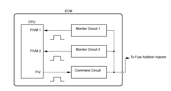
| P2047 | With the exhaust fuel addition injector off, the FIVM1 output is high and the FIVM2 output is low for 3 seconds. (1-trip detection logic) |
|
| P2048 | With the exhaust fuel addition injector off, the FIVM1 output is high and the FIVM2 output is high for 0.16 seconds. (1-trip detection logic) | |
| P2049 | With the exhaust fuel addition injector on, the FIVM1 output is low and the FIVM2 output is low for 7 or more times. (1-trip detection logic) |
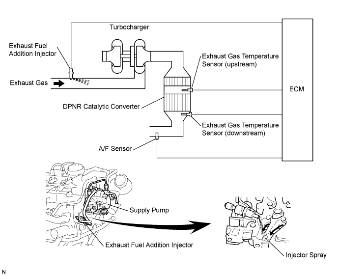
| 1.INSPECT EXHAUST FUEL ADDITION INJECTOR ASSEMBLY |
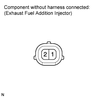 |
Disconnect the exhaust fuel addition injector connector.
Measure the resistance according to the value(s) in the table below.
| Tester Connection | Condition | Specified Condition |
| 1 - 2 | 20°C (68°F) | 7.1 to 7.9 Ω |
Reconnect the exhaust fuel addition injector connector.
|
| ||||
| OK | |
| 2.CHECK FUSE (EFI NO. 2 FUSE) |
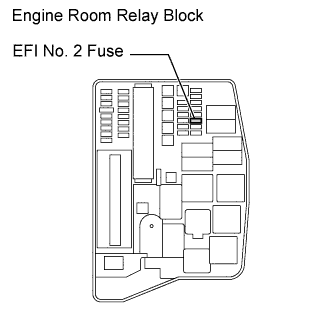 |
Remove the EFI No. 2 fuse from the engine room relay block.
Measure the resistance according to the value(s) in the table below.
| Tester Connection | Condition | Specified Condition |
| EFI No. 2 fuse | Always | Below 1 Ω |
Reinstall the EFI No. 2 fuse.
|
| ||||
| OK | |
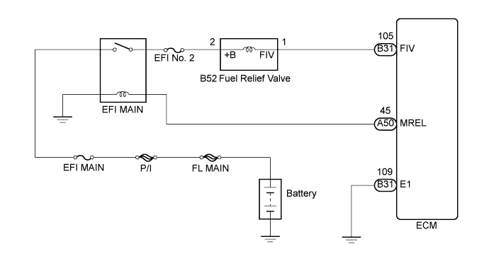
| 3.CHECK HARNESS AND CONNECTOR (EXHAUST FUEL ADDITION INJECTOR ASSEMBLY - ECM) |
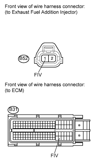 |
Disconnect the exhaust fuel addition injector assembly connector.
Disconnect the ECM connector.
Measure the resistance according to the value(s) in the table below.
| Tester Connection | Condition | Specified Condition |
| B52-1 (FIV) - B31-105 (FIV) | Always | Below 1 Ω |
| Tester Connection | Condition | Specified Condition |
| B52-1 (FIV) or B31-105 (FIV) - Body ground | Always | 10 kΩ or higher |
Reconnect the exhaust fuel addition injector assembly connector.
Reconnect the ECM connector.
|
| ||||
| OK | |
| 4.CHECK HARNESS AND CONNECTOR (EXHAUST FUEL ADDITION INJECTOR ASSEMBLY - EFI MAIN RELAY) |
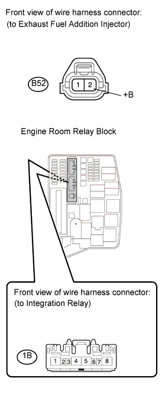 |
Disconnect the exhaust fuel addition injector assembly connector.
Remove the integration relay from the engine room relay block.
Disconnect the integration relay connector.
Measure the resistance according to the value(s) in the table below.
| Tester Connection | Condition | Specified Condition |
| B52-2 (+B) - 1B-4 | Always | Below 1 Ω |
| Tester Connection | Condition | Specified Condition |
| B52-2 (+B) or 1B-4 - Body ground | Always | 10 kΩ or higher |
Reconnect the exhaust fuel addition injector assembly connector.
Reconnect the integration relay connector.
Reinstall the integration relay.
|
| ||||
| OK | ||
| ||
