АВТОМАТИЧЕСКАЯ ТРАНСМИССИЯ В БЛОКЕ С ГЛАВНОЙ ПЕРЕДАЧЕЙ > СНЯТИЕ |
| 1. DISCHARGE FUEL SYSTEM PRESSURE |
| 2. PLACE FRONT WHEELS FACING STRAIGHT AHEAD |
| 3. REMOVE FRONT WHEELS |
| 4. REMOVE ENGINE UNDER COVER REAR LH |
| 5. REMOVE ENGINE UNDER COVER REAR RH |
| 6. REMOVE NO. 1 ENGINE UNDER COVER |
| 7. REMOVE NO. 2 ENGINE UNDER COVER |
| 8. DRAIN ENGINE COOLANT |
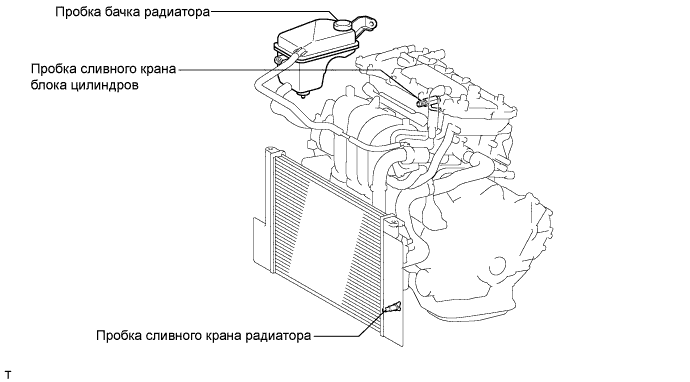
Loosen the radiator drain cock plug.
Remove the radiator reservoir cap.
Loosen the cylinder block drain cock plug.
| 9. DRAIN AUTOMATIC TRANSAXLE FLUID |
Remove the drain plug and gasket, and drain ATF.
Install a new gasket and the drain plug.
| 10. REMOVE UPPER RADIATOR AIR DEFLECTOR |
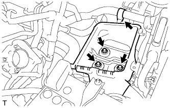
| 11. REMOVE NO. 2 CYLINDER HEAD COVER |
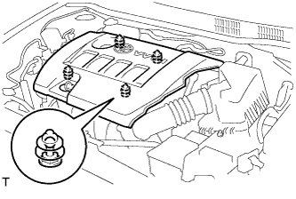 |
Hold the rear of the cover and raise it to disengage the 2 clips on the front of the cover. Continue to raise the cover to disengage the 2 clips on the front of the cover and remove the cover.
| 12. REMOVE AIR CLEANER CAP SUB-ASSEMBLY |
Disconnect the mass air flow meter connector.
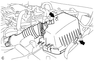 |
Disconnect the 2 clamps.
 |
Disconnect the band and ventilation hose, and remove the air cleaner cap sub-assembly.
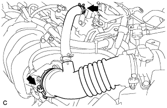
| 13. REMOVE AIR CLEANER CASE |
Separate the air cleaner filter element from the air cleaner.
 |
Remove the 3 bolts from the air cleaner case.
| 14. REMOVE BATTERY |
Disconnect the battery terminal.
Remove the bolt and loosen the nut.
Remove the battery.
| 15. REMOVE BATTERY CARRIER |
 |
Separate the wire harness clamp from the battery carrier.
 |
Remove the 2 bolts.
Separate the radiator pipe from the battery carrier.
Remove the 4 bolts and battery carrier.
| 16. SEPARATE RADIATOR HOSE INLET |
 |
Separate the radiator hose from the cylinder head.
| 17. SEPARATE RADIATOR HOSE OUTLET |
 |
Separate the radiator hose from the water inlet hose.
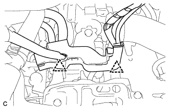
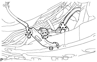
| 18. DISCONNECT TRANSMISSION CONTROL CABLE ASSEMBLY |
 |
Disconnect the control cable from the control cable support.
Remove the nut and disconnect the control cable from the control shaft lever.
Remove the clip and disconnect the control cable from the control cable bracket.
Remove the bolt and disconnect the clamp of the control cable.
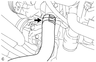
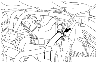
| 19. DISCONNECT OIL COOLER HOSE |
 |
Disconnect the 2 oil cooler hoses from the automatic transaxle.
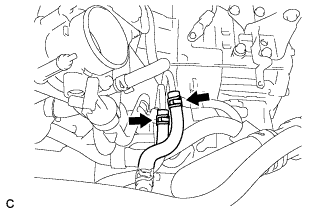
| 20. DISCONNECT HEATER OUTLET WATER HOSE |
 |
Disconnect the heater outlet water hose from the heater unit.
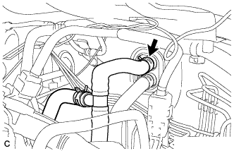
| 21. DISCONNECT HEATER INLET WATER HOSE |
 |
Disconnect the heater inlet water hose from the heater unit.
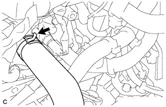
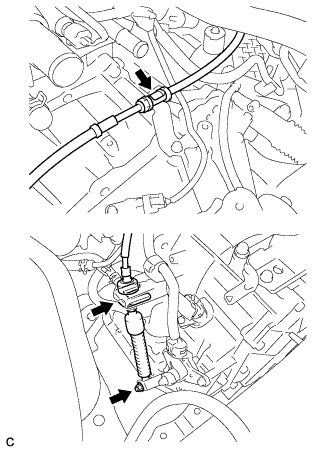
| 22. DISCONNECT FUEL TUBE SUB-ASSEMBLY |
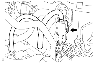 |
Release the claw and remove the No. 1 fuel pipe clamp.
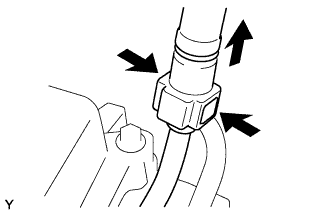 |
Pinch the retainer as illustrated, then pull the fuel tube connector out of the pipe.
| 23. REMOVE V-RIBBED BELT |
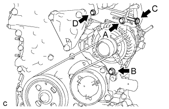 |
Loosen bolts A and B.
Loosen bolt C, then remove the V-ribbed belt.
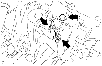
| 24. REMOVE GENERATOR ASSEMBLY |
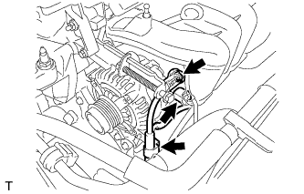 |
Remove the terminal cap.
Remove the nut and disconnect the wire harness from terminal B.
Disconnect the connector and harness clamp.
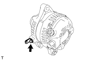
 |
Remove the 2 bolts and generator assembly.
 |
Remove the bolt and wire harness clamp bracket.
| 25. SEPARATE COMPRESSOR WITH PULLEY ASSEMBLY (w/ Air Conditioning System) |
Disconnect the connector.
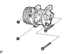 |
Remove the 2 bolts and 2 nuts.
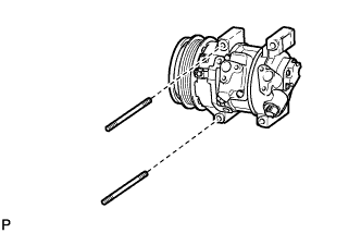 |
Using a "TORX" socket wrench (E8), remove the 2 stud bolts and compressor assembly with pulley.
| 26. DISCONNECT WIRE HARNESS |
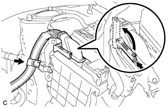 |
Pull up the lever and disconnect the connector of the engine control computer.
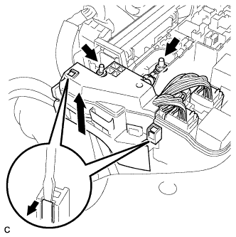 |
Remove the 2 nuts.
Remove the connector and 2 clamps from the engine room junction block and disconnect the wire harness.
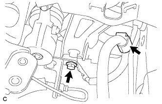 |
Remove the bolt and clamp (for Manual Transaxle).
 |
Remove the bolt and clamp. (for Automatic Transaxle).
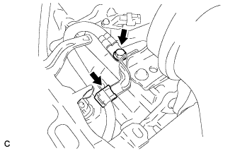
Disconnect all the wire harnesses and connectors.
Make sure that no wire harness is connected between the body and engine.
| 27. SECURE STEERING WHEEL |
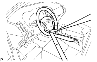 |
Для предотвращения вращения рулевого колеса закрепите его ремнем безопасности.
| 28. REMOVE COLUMN HOLE COVER SILENCER SHEET |
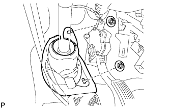 |
Оттяните напольный коврик, освободите 2 фиксатора и снимите шумоизолирующую накладку кожуха выходного отверстия рулевой колонки.
| 29. SEPARATE NO. 2 STEERING INTERMEDIATE SHAFT ASSEMBLY |
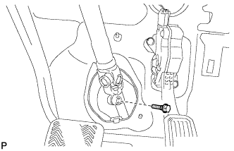 |
Выверните болт.
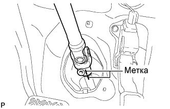 |
Нанесите метки на промежуточный вал № 2 рулевого управления в сборе и промежуточный вал рулевого управления.
Отсоедините промежуточный вал № 2 рулевого управления в сборе от промежуточного вала рулевого управления.
| 30. DISCONNECT NO. 1 STEERING COLUMN HOLE COVER SUB-ASSEMBLY |
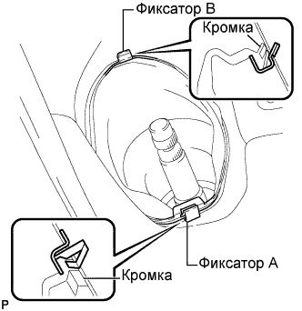 |
Снимите фиксатор A и кожух выходного отверстия рулевой колонки № 1 в сборе и отделите фиксатор B от кузова.
| 31. REMOVE HEATED OXYGEN SENSOR |
Disconnect the oxygen sensor connector.
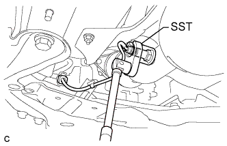 |
Using SST, remove the oxygen sensor from the front exhaust pipe assembly.
| 32. REMOVE FRONT EXHAUST PIPE ASSEMBLY |
 |
Remove the 2 bolts and 2 compression springs.
 |
Remove the 2 bolts and 2 compression springs.
Remove the exhaust pipe support, and then remove the front exhaust pipe assembly.
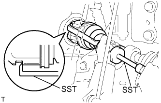
| 33. REMOVE FRONT AXLE HUB LH NUT |
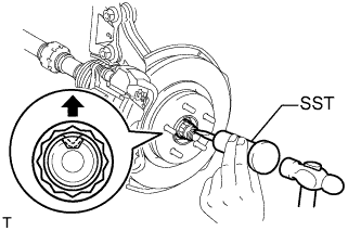 |
С помощью SST и молотка освободите накерненную часть гайки ступицы переднего колеса.
Включив тормоза, снимите гайку ступицы переднего колеса.
| 34. REMOVE FRONT AXLE HUB RH NUT |
| 35. DISCONNECT FRONT SPEED SENSOR LH |
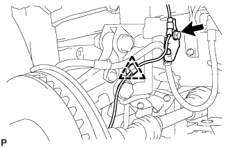 |
Выверните болт, снимите зажим и отсоедините передний датчик частоты вращения.
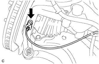 |
Выверните болт и отсоедините передний датчик частоты вращения от поворотного кулака.
| 36. DISCONNECT FRONT SPEED SENSOR RH |
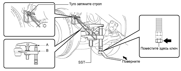
| 37. SEPARATE TIE ROD END SUB-ASSEMBLY LH |
Снимите шплинт и отверните гайку.
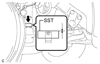 |
Установите SST на наконечник рулевой тяги.
При помощи SST отсоедините наконечник тяги от поворотного кулака.
| 38. SEPARATE TIE ROD END SUB-ASSEMBLY RH |
| 39. SEPARATE FRONT STABILIZER LINK ASSEMBLY LH |
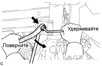 |
Отверните гайку и отсоедините стойку стабилизатора в сборе от переднего амортизатора с цилиндрической винтовой пружиной.
| 40. SEPARATE FRONT STABILIZER LINK ASSEMBLY RH |
| 41. SEPARATE FRONT SUSPENSION ARM SUB-ASSEMBLY LOWER NO. 1 LH |
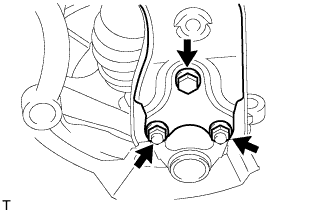 |
Выверните болт и отверните 2 гайки.
Отсоедините нижний рычаг передней подвески от переднего нижнего шарового шарнира.
| 42. SEPARATE FRONT SUSPENSION ARM SUB-ASSEMBLY LOWER NO. 1 RH |
| 43. SEPARATE STEERING KNUCKLE WITH AXLE HUB LH |
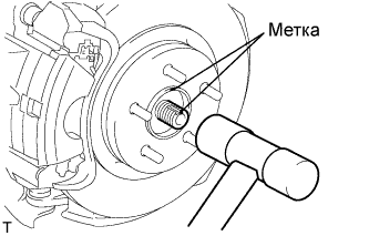 |
Нанесите метки на приводной вал и ступицу колеса.
С помощью молотка с пластмассовым покрытием отсоедините левую переднюю полуось в сборе.
| 44. SEPARATE STEERING KNUCKLE WITH AXLE HUB RH |
| 45. REMOVE FRONT DRIVE SHAFT ASSEMBLY LH |
 |
С помощью SST снимите передний приводной вал.
| 46. REMOVE FRONT DRIVE SHAFT ASSEMBLY RH |
| 47. REMOVE FLYWHEEL HOUSING UNDER COVER |
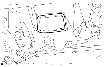 |
Remove the flywheel housing under cover.
| 48. REMOVE DRIVE PLATE AND TORQUE CONVERTER CLUTCH SETTING BOLT |
 |
Remove the 6 torque converter set bolts while holding the crankshaft pulley bolt with a wrench.
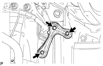
| 49. REMOVE ENGINE FRONT MOUNTING BRACKET REINFORCEMENT LOWER |
 |
Выверните 2 болта и снимите нижнее усиление кронштейна передней опоры двигателя.
| 50. REMOVE FRONT SUSPENSION MEMBER REINFORCEMENT LH |
 |
Выверните 4 болта и снимите левое усиление элемента передней подвески.
| 51. REMOVE FRONT SUSPENSION MEMBER REINFORCEMENT RH |
 |
Выверните 4 болта и снимите правое усиление элемента передней подвески.
| 52. REMOVE FRONT SUSPENSION MEMBER REAR BRACE LH |
 |
Выверните 3 болта и снимите левую заднюю скобу элемента передней подвески.
| 53. REMOVE FRONT SUSPENSION MEMBER REAR BRACE RH |
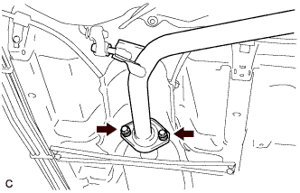
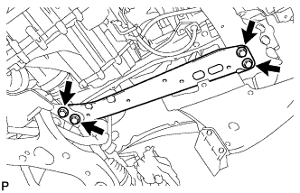
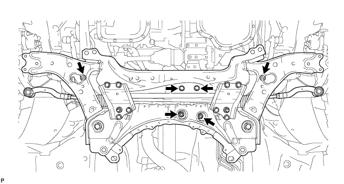
| 54. REMOVE FRONT SUSPENSION CROSSMEMBER SUB-ASSEMBLY |
 |
Отцепите 2 зажима и захват, и отсоедините жгут проводов кислородного датчика от подрамника передней подвески в сборе.
Подоприте подрамник передней подвески телескопическим гидравлическим домкратом.
Выверните 4 болта, отверните 2 гайки и снимите подрамник передней подвески в сборе.
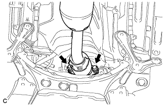
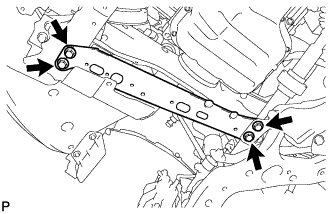
| 55. REMOVE FRONT CROSSMEMBER |
 |
Remove the bolt and nut.
Remove the engine mounting insulator front from the engine mounting bracket front.
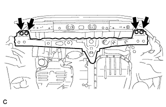 |
Remove the 4 bolts and front crossmember.
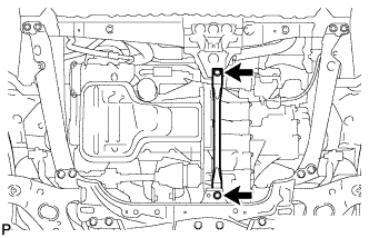
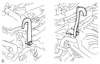
| 56. REMOVE ENGINE ASSEMBLY WITH TRANSAXLE |
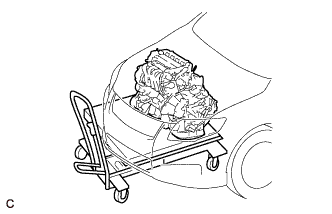 |
Set the engine lifter.
 |
Remove the 2 bolts and nut, and separate the engine mounting insulator RH.
 |
Remove the bolt and nut, and separate the engine mounting insulator LH.
Carefully remove the engine with transaxle from the vehicle.
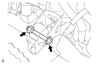
| 57. REMOVE REAR ENGINE MOUNTING INSULATOR |
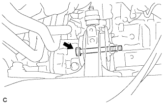 |
Remove the bolt and nut, and separate the rear engine mounting insulator.
| 58. INSTALL ENGINE HANGER |
Remove the air fuel ratio sensor bracket.
 |
Install the 2 engine hangers with the 2 bolts.
| Part Name | Part No. |
| No. 1 engine hanger | 12281-37020 |
| No. 2 engine hanger | 12282-37010 |
| Bolt | 91552-81050 |
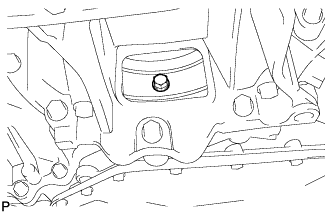
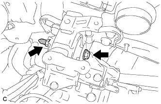
| 59. REMOVE FLYWHEEL HOUSING SIDE COVER |
| 60. REMOVE STARTER ASSEMBLY |
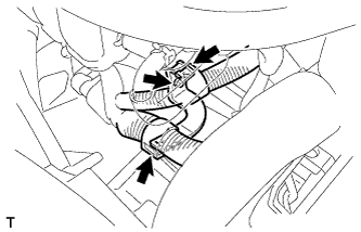 |
Separate the 2 harness clamps.
Remove the bolt and wire harness bracket.
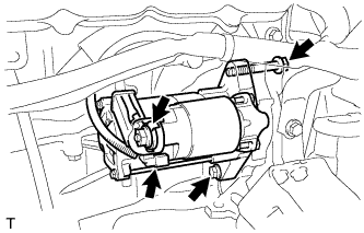 |
Remove the terminal cap.
Remove the nut and terminal 30.
Disconnect the connector.
Remove the 2 bolts and starter assembly.
| 61. SEPARATE AUTOMATIC TRANSAXLE ASSEMBLY |
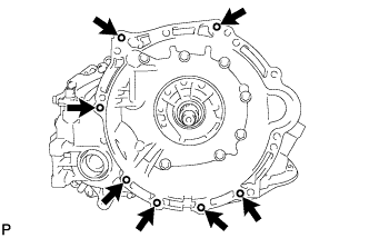 |
Remove the 7 bolts and remove the automatic transaxle from the engine.
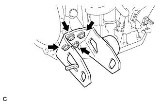
| 62. REMOVE ENGINE MOUNTING BRACKET LH |
 |
Remove the 3 bolts and remove the engine mounting bracket LH from the automatic transaxle.
| 63. REMOVE ENGINE MOUNTING FRONT BRACKET |
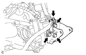
 |
Remove the 4 bolts and remove the engine mounting front bracket from the automatic transaxle.
| 64. REMOVE ENGINE MOUNTING REAR BRACKET |
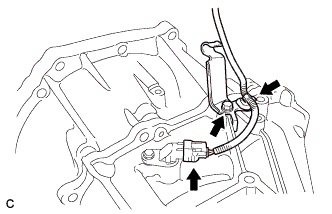
 |
Separate the wire harness clamp and remove the wire harness from the engine mounting rear bracket.
Remove the 3 bolts and remove the engine mounting rear bracket from the automatic transaxle.
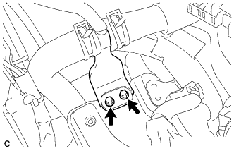
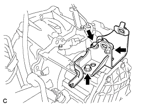
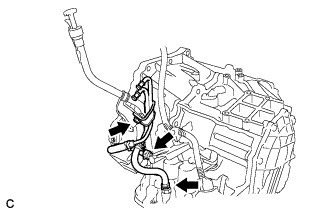
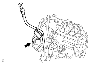
| 65. REMOVE TRANSMISSION CONTROL CABLE SUPPORT |
 |
Separate the speed sensor connector and transmission control cable support and remove the wire harness from the automatic transaxle.
Remove the bolt and remove the transmission control cable bracket from the automatic transaxle.
| 66. REMOVE OIL COOLER TUBE SUB-ASSEMBLY |
 |
Remove the 2 hose clamps and bolt and remove the oil cooler tube sub-assembly.
| 67. REMOVE OIL LEVEL GAUGE GUIDE |
 |
Remove the oil level gauge sub-assembly.
Remove the bolt and remove the oil level gauge guide.
Remove the O-ring from the oil level gauge guide.
| 68. REMOVE NO. 1 TRANSMISSION CONTROL CABLE BRACKET |
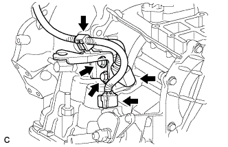 |
Separate the 2 connectors and the wire harness clamp, and remove the wire harness from the automatic transaxle.
Remove the 2 bolts and remove the No. 1 transmission control cable bracket from the automatic transaxle.
| 69. REMOVE SPEEDOMETER DRIVEN HOLE COVER SUB-ASSEMBLY |
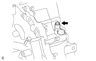 |
Remove the bolt and speedometer driven hole cover sub-assembly.
| 70. REMOVE TORQUE CONVERTER CLUTCH ASSEMBLY |
Remove the torque converter clutch from the automatic transaxle.
