DTC P1426 Differential Pressure Sensor Installation Error |
| DTC No. | DTC Detection Condition | Trouble Area |
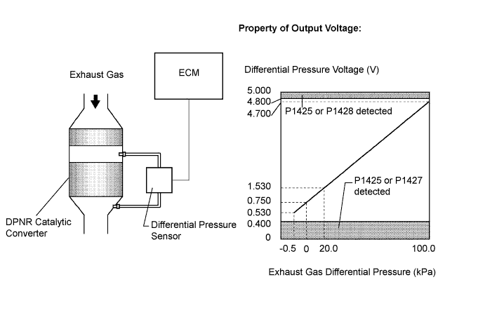
| P1426 | When output voltage from the differential pressure sensor indicates positive pressure as negative pressure (and vice versa) (1-trip detection logic) |
|
| Condition | Differential Pressure Output | Sensor Condition |
| Ignition switch on (IG) | Approximately 0 kPa | Normal |
| Always | 3 kPa | Open or short circuit |
| 3000 rpm (No engine load) | Negative output | Incorrect arrangement of hose piping |
| 1.CHECK OTHER DTC OUTPUT (IN ADDITION TO DTC P1426) |
Connect the intelligent tester to the DLC3.
Turn the ignition switch on (IG).
Turn the tester on.
Enter the following menu items: Powertrain / Engine and ECT / DTC.
Read the DTCs.
| Result | Proceed to |
| DTC P1426 is output | A |
| DTC P1426 and other DTCs are output | B |
|
| ||||
| A | |
| 2.CHECK CONNECTION OF VACUUM HOSE (DIFFERENTIAL PRESSURE SENSOR - VACUUM TRANSMITTING PIPE) |
Check if vacuum hose routing between the differential pressure sensor and the vacuum transmitting pipe is correct.
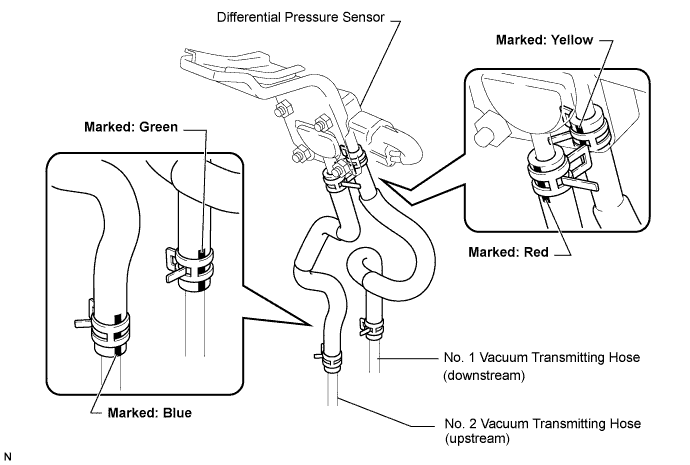
Check that there is no exhaust gas leakage between the differential pressure sensor and the vacuum transmitting pipe.
|
| ||||
| OK | |
| 3.CHECK BLOCKAGE OF VACUUM HOSE AND TRANSMITTING PIPE |
Disconnect the vacuum hose (both upstream and downstream) on the differential pressure sensor.
Start the engine.
Check if there are exhaust gas pulsations from both vacuum hoses during idling.
|
| ||||
| OK | |
| 4.READ VALUE OF DIFFERENTIAL PRESSURE |
Connect the intelligent tester to the DLC3.
Turn the ignition switch on (IG).
Turn the tester on.
Enter the following menu items: Powertrain / Engine and ECT / Data List / DPF Differential Pressure.
Check that differential pressure is within the specification below.
| Condition | Differential Pressure Output | Sensor Condition |
| Ignition switch on (IG) | Approximately 0 kPa | Normal |
| Always | 3 kPa | Open or short circuit |
| 3000 rpm (No engine load) | Negative output | Incorrect arrangement of hose piping |
|
| ||||
| OK | ||
| ||
