ТРОС МЕХАНИЗМА ПЕРЕКЛЮЧЕНИЯ ПЕРЕДАЧ (для моделей производства TMUK, TMMT с кузовом типа "хэтчбэк") > УСТАНОВКА |
| 1. INSTALL TRANSMISSION CONTROL CABLE ASSEMBLY |
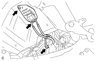 |
Install the transmission control cable assembly with the 2 nuts and bolt.
 |
Install the transmission control cable assembly to the control cable bracket with 2 new clips.
Install the transmission control cable assembly to the transaxle with the 2 clips.
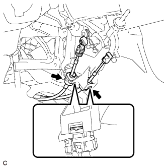 |
Engage the 2 claws, and install the transmission control cable assembly to the shift lever assembly.
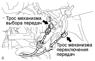 |
Install the control select cable to the shift lever assembly.
Install the control shift cable to the shift lever assembly.
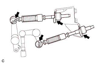
| 2. ADJUST TRANSMISSION CONTROL SELECT CABLE |
Install the transmission control cable assembly to the manual transaxle.
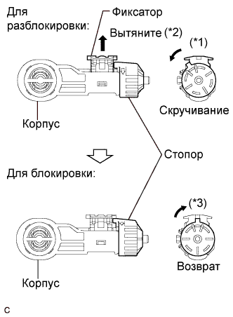 |
Release the lock of the cable length adjustment structure of the select cable.
Twist the stopper. (*1)
Pull the lock piece outward from the case to release the lock. (*2)
Return the stopper. (*3)
Install the transmission control cable assembly to the shift lever assembly.
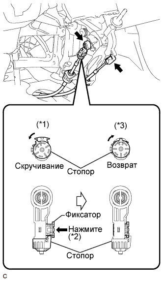 |
Lock the cable length adjustment structure of the select cable.
Twist the stopper. (*1)
Push the lock piece into the case. (*2)
Return the stopper to prevent the lock from being released. (*3)
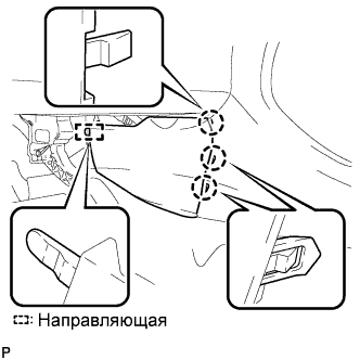
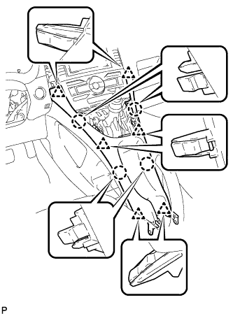
| 3. INSTALL LOWER NO. 1 INSTRUMENT PANEL FINISH PANEL |
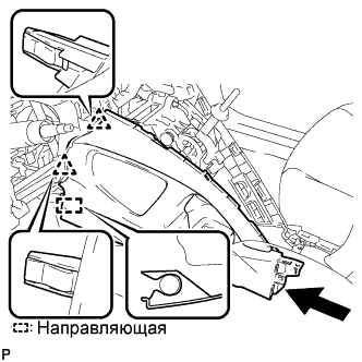 |
Введите в зацепление 2 захвата и направляющую.
 |
Введите в зацепление 4 захвата и 2 направляющие.
 |
Установите нижнюю отделочную накладку панели приборов № 1 и закрепите ее 2 винтами <E> или <F>.
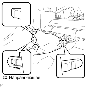
| 4. INSTALL LOWER NO. 2 INSTRUMENT PANEL FINISH PANEL |
 |
Введите в зацепление 2 захвата и направляющую.
 |
Установите нижнюю отделочную накладку панели приборов № 2 и закрепите ее 2 винтами <E> или <F>.
| 5. INSTALL INSTRUMENT PANEL UNDER TRAY |
 |
Установите нижний лоток панели приборов и закрепите его 4 захватами.
| 6. INSTALL FRONT NO. 1 CONSOLE BOX INSERT |
 |
Введите в зацепление направляющую.
Введите в зацепление 3 захвата и установите переднюю вставку вещевого ящика в облицовке туннеля пола № 1.
| 7. INSTALL FRONT NO. 2 CONSOLE BOX INSERT |
 |
Введите в зацепление направляющую.
Введите в зацепление 3 захвата и установите переднюю вставку вещевого ящика в облицовке туннеля пола № 2.
| 8. INSTALL REAR CONSOLE BOX ASSEMBLY (w/o Console Box Lid) |
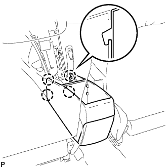 |
Введите в зацепление 4 захвата.
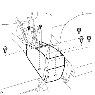 |
Установите вещевой ящик в облицовке туннеля пола и закрепите его 4 болтами и 2 винтами.
| 9. INSTALL REAR CONSOLE BOX ASSEMBLY (w/ Console Box Lid) |
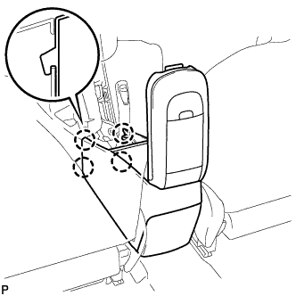 |
Введите в зацепление 4 захвата.
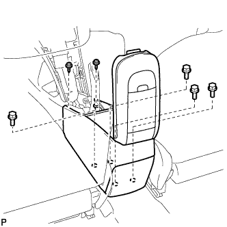 |
Установите вещевой ящик в облицовке туннеля пола и закрепите его 4 болтами и 2 винтами.
| 10. INSTALL CONSOLE BOX CARPET (w/o Console Box Lid) |
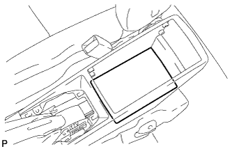 |
Установите коврик вещевого ящика в облицовке туннеля пола.
| 11. INSTALL CONSOLE BOX CARPET (w/ Console Box Lid) |
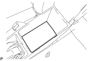 |
Установите коврик вещевого ящика в облицовке туннеля пола.
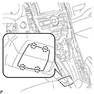
| 12. INSTALL CENTER LOWER INSTRUMENT PANEL FINISH PANEL ASSEMBLY |
 |
Введите в зацепление 4 захвата и 6 фиксаторов и установите центральную нижнюю облицовочную накладку панели приборов.
| 13. INSTALL UPPER CONSOLE PANEL |
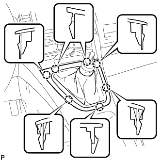 |
Введите в зацепление 7 захватов и установите верхнюю облицовку панели пола.
| 14. INSTALL REAR CONSOLE BOX COVER |
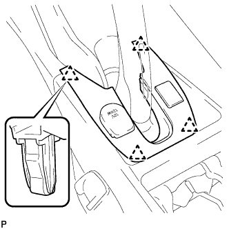 |
Подсоедините разъем.
Установите крышку вещевого ящика в облицовке туннеля пола и закрепите ее 4 фиксаторами.
| 15. INSTALL SHIFT LEVER KNOB SUB-ASSEMBLY |
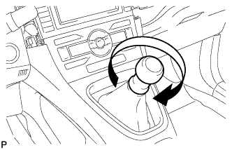 |
Поверните рукоятку рычага переключения передач по часовой стрелке и закрепите ее.
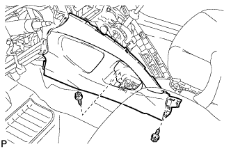
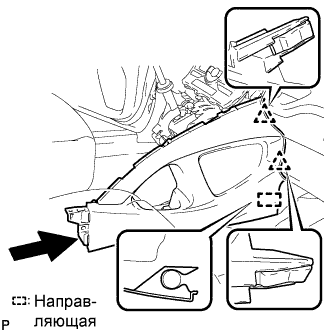
| 16. INSTALL INSTRUMENT PANEL FINISH PANEL END LH |
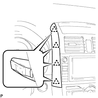 |
Введите в зацепление 4 фиксатора и установите левую отделочную накладку панели приборов.
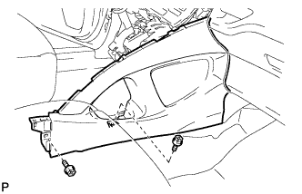
| 17. INSTALL INSTRUMENT PANEL FINISH PANEL END RH |
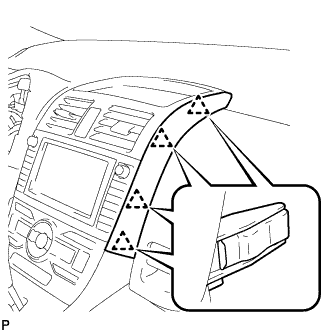 |
Введите в зацепление 4 фиксатора и установите правую отделочную накладку панели приборов.
| 18. INSTALL NO. 1 FRONT FLOOR HEAT INSULATOR |
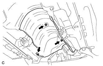 |
Install the No. 1 front floor heat insulator with the 3 nuts.
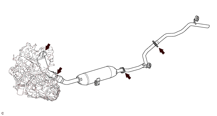
| 19. INSTALL FRONT EXHAUST PIPE ASSEMBLY (for 1ND-TV) |
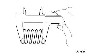 |
Using vernier calipers, measure the free length of the compression springs.
| Minimum (front) | 41.5 mm (1.63 in.) |
| Minimum (rear) | 38.5 mm (1.52 in.) |
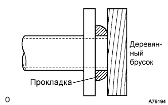 |
Using a plastic hammer and wooden block, tap in a new exhaust pipe gasket until its surface is flush with the exhaust manifold converter sub-assembly.
 |
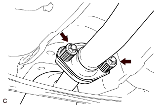
Install the exhaust pipe supports, then install the front exhaust pipe assembly with the 2 compression springs and 2 bolts.
|
Using a plastic hammer and wooden block, tap in a new exhaust pipe gasket until its surface is flush with the front exhaust pipe assembly.
 |
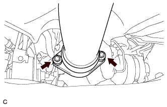
Install the 2 compression springs and 2 bolts, then connect the front exhaust pipe assembly to the center exhaust pipe assembly.
| 20. INSTALL NO. 1 AIR TUBE |
 |
Install the No. 1 air tube with the 3 bolts, and tighten the 2 hose clamps.
| 21. INSTALL AIR CLEANER CASE SUB-ASSEMBLY (for 1ND-TV) |
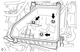 |
Install the air cleaner case sub-assembly with the 3 bolts.
| 22. INSTALL AIR CLEANER CAP SUB-ASSEMBLY (for 1ND-TV) |
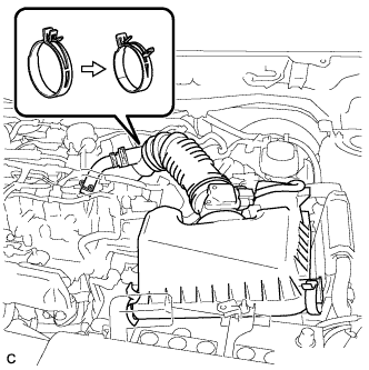 |
Install the air cleaner cap sub-assembly, and connect the 2 clamps and band.
Connect the No. 2 ventilation hose.
Connect the mass air flow meter connector.
| 23. INSTALL BATTERY (for 1ND-TV) |
Install the battery and battery tray.
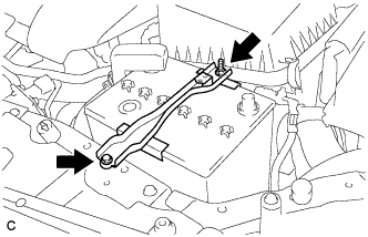 |
Install the battery clamp with the bolt and nut.
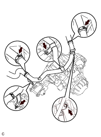
| 24. INSPECT FOR EXHAUST GAS LEAK (for 1ND-TV) |
Check that there are no exhaust gas leaks from the points (jointed parts of the exhaust pipes and installed parts of each sensor) shown in the illustration.