ТРОС МЕХАНИЗМА ПЕРЕКЛЮЧЕНИЯ ПЕРЕДАЧ В СБОРЕ (для моделей с кузовом типа "хэтчбэк") > УСТАНОВКА |
| 1. INSTALL TRANSMISSION CONTROL CABLE ASSEMBLY |
 |
Put the transmission control cable into the cabin and connect the transmission control cable with the 2 nuts.
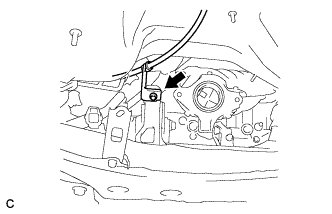 |
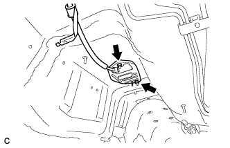
Install the transmission control cable support to the rear engine mounting insulator with the bolt.
 |
Connect the transmission control cable to the transmission control cable bracket with a new clip.
Connect the transmission control cable to the control shaft lever with the nut.
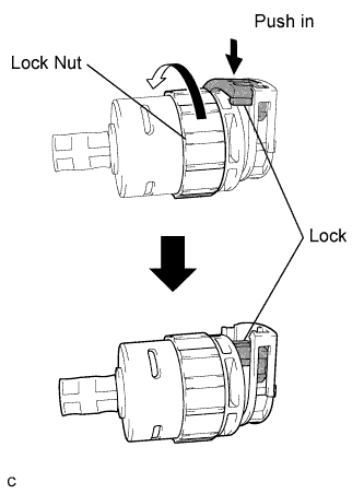 |
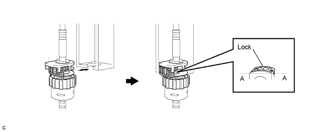
Turn the lock nut of the transmission control cable counterclockwise. While holding the lock nut, push in the lock.
Connect the outer part of the transmission control cable to the shift lever retainer.
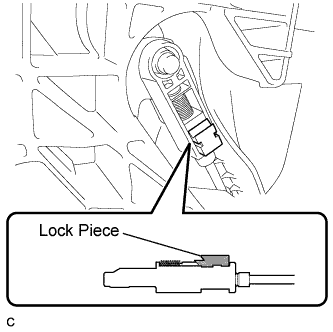 |
Install the transmission control cable end to the shift lever assembly.
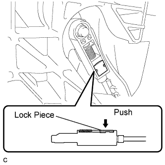 |
Push the lock piece into the adjuster case.
| 2. INSTALL NO. 1 FRONT FLOOR HEAT INSULATOR |
 |
Install the No. 1 front floor heat insulator with the 3 nuts.
| 3. INSTALL FRONT EXHAUST PIPE ASSEMBLY |
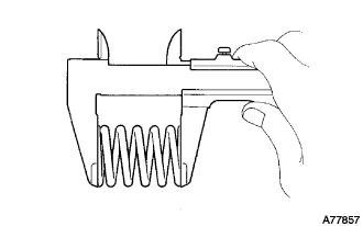 |
Using vernier calipers, measure the free length of the compression springs.
| Minimum (front) | 41.5 mm (1.63 in.) |
| Minimum (rear) | 38.5 mm (1.52 in.) |
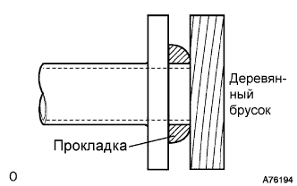 |
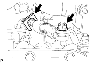
Using a plastic hammer and wooden block, tap in a new gasket until its surface is flush with the exhaust manifold.
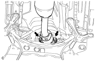 |
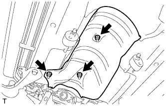
Install the exhaust pipe support, and then install the front exhaust pipe assembly with the 2 compression springs and 2 bolts.
|
Using a plastic hammer and wooden block, tap in a new gasket until its surface is flush with the front exhaust pipe assembly.
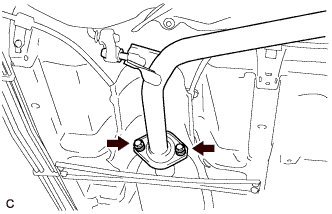 |
Connect the front exhaust pipe assembly to the center exhaust pipe assembly with the 2 compression springs and 2 bolts.
| 4. INSTALL OXYGEN SENSOR |
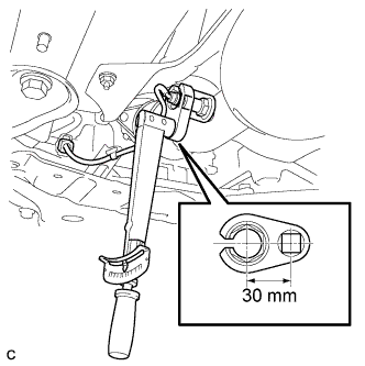 |
Using SST, install the oxygen sensor to the front exhaust pipe assembly.
Connect the oxygen sensor connector.
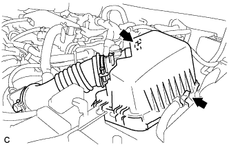
| 5. INSTALL AIR CLEANER CASE |
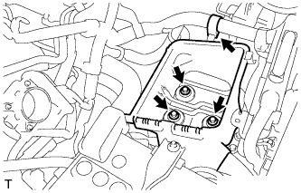 |
Install the air cleaner case with the 3 bolts.
Install the wire harness clamp to the air cleaner case.
Install the air cleaner filter element.
| 6. INSTALL AIR CLEANER CAP SUB-ASSEMBLY |
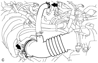 |
Connect the air cleaner cap sub-assembly with the band.
Connect the ventilation hose.
 |
Connect the 2 clamps.
Connect the mass air flow meter connector.
| 7. INSTALL NO.2 CYLINDER HEAD COVER |
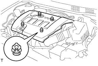 |
Engage the 4 clips to install the V-bank cover.
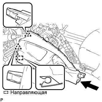
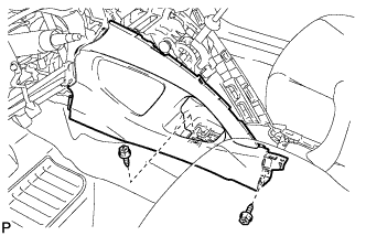
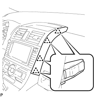
| 8. INSTALL LOWER NO. 2 INSTRUMENT PANEL FINISH PANEL |
 |
Введите в зацепление 2 захвата и направляющую.
 |
Установите нижнюю отделочную накладку панели приборов № 2 и закрепите ее 2 винтами <E> или <F>.
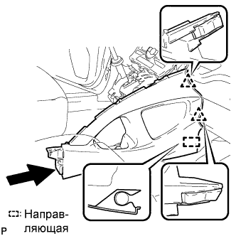
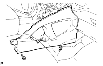
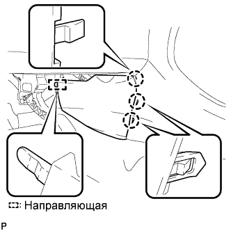
| 9. INSTALL LOWER NO. 1 INSTRUMENT PANEL FINISH PANEL |
 |
Введите в зацепление 2 захвата и направляющую.
 |
Введите в зацепление 4 захвата и 2 направляющие.
 |
Установите нижнюю отделочную накладку панели приборов № 1 и закрепите ее 2 винтами <E> или <F>.
| 10. INSTALL INSTRUMENT PANEL UNDER TRAY |
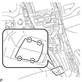 |
Установите нижний лоток панели приборов и закрепите его 4 захватами.
| 11. INSTALL FRONT NO. 1 CONSOLE BOX INSERT |
 |
Введите в зацепление направляющую.
Введите в зацепление 3 захвата и установите переднюю вставку вещевого ящика в облицовке туннеля пола № 1.
| 12. INSTALL FRONT NO. 2 CONSOLE BOX INSERT |
 |
Введите в зацепление направляющую.
Введите в зацепление 3 захвата и установите переднюю вставку вещевого ящика в облицовке туннеля пола № 2.
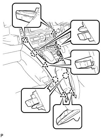
| 13. INSTALL REAR CONSOLE BOX ASSEMBLY (w/o Console Box Lid) |
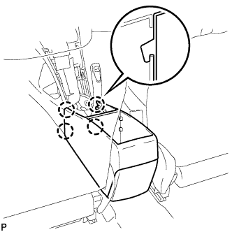 |
Введите в зацепление 4 захвата.
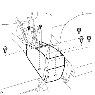 |
Установите вещевой ящик в облицовке туннеля пола и закрепите его 4 болтами и 2 винтами.
| 14. INSTALL REAR CONSOLE BOX ASSEMBLY (w/ Console Box Lid) |
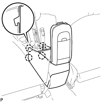 |
Введите в зацепление 4 захвата.
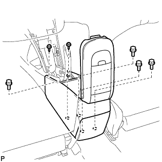 |
Установите вещевой ящик в облицовке туннеля пола и закрепите его 4 болтами и 2 винтами.
| 15. INSTALL CONSOLE BOX CARPET (w/o Console Box Lid) |
 |
Установите коврик вещевого ящика в облицовке туннеля пола.
| 16. INSTALL CONSOLE BOX CARPET (w/ Console Box Lid) |
 |
Установите коврик вещевого ящика в облицовке туннеля пола.
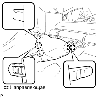
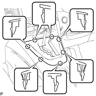
| 17. INSTALL LOWER CENTER INSTRUMENT PANEL FINISH PANEL |
 |
Введите в зацепление 4 захвата и 6 фиксаторов.
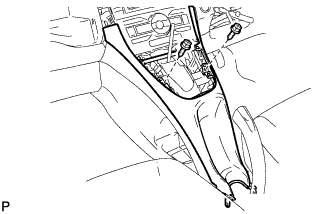 |
Установите центральную нижнюю облицовочную накладку панели приборов и закрепите ее 2 винтами <E> или <F>.
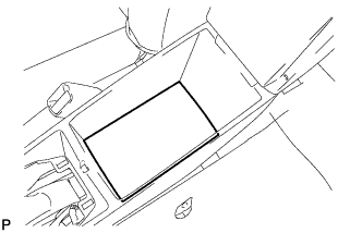
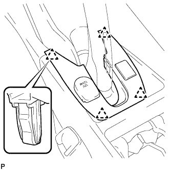
| 18. INSTALL POSITION INDICATOR HOUSING ASSEMBLY |
 |
Введите в зацепление 7 захватов и установите корпус индикатора положения в сборе.
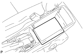
| 19. INSTALL REAR CONSOLE BOX COVER |
 |
Подсоедините разъем.
Установите крышку вещевого ящика в облицовке туннеля пола и закрепите ее 4 фиксаторами.
| 20. INSTALL SHIFT LEVER KNOB SUB-ASSEMBLY |
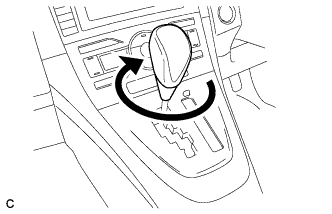 |
Install the shift lever knob sub-assembly.
| 21. INSTALL INSTRUMENT PANEL FINISH PANEL END LH |
 |
Введите в зацепление 4 фиксатора и установите левую отделочную накладку панели приборов.
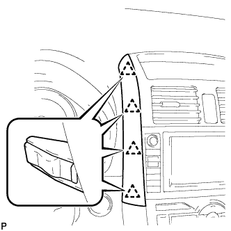
| 22. INSTALL INSTRUMENT PANEL FINISH PANEL END RH |
 |
Введите в зацепление 4 фиксатора и установите правую отделочную накладку панели приборов.
| 23. CONNECT CABLE TO NEGATIVE BATTERY TERMINAL |
| 24. INSPECT SHIFT LEVER POSITION |
When moving the lever from the P position to the R position with the ignition switch on (IG) and the brake pedal depressed, make sure that the shift lever moves smoothly and moves correctly into position.
Start the engine and make sure that the vehicle moves forward when moving the lever from the N position to the D position and moves rearward when moving the lever to the R position. If the operation cannot be performed as specified, inspect the park/neutral position switch assembly and check the shift lever assembly installation condition.
| 25. ADJUST SHIFT LEVER POSITION |
Apply the parking brake and move the shift lever to the N position.
Remove the lower instrument panel finish panel (See page Нажмите здесь).
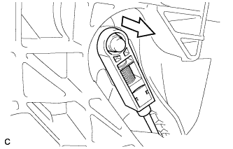 |
Disconnect the end of the transmission control cable assembly from the shift lever assembly.
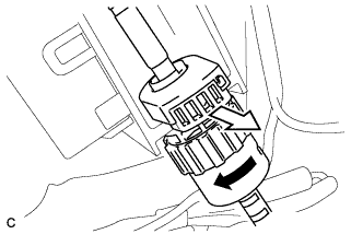 |
Turn the lock nut counterclockwise. While holding the lock nut, disconnect the transmission control cable from the shift lever retainer.
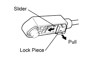 |
Slide the slider of the transmission control cable in the direction indicated by the arrow and pull the lock piece outward.
Connect the outer part of the transmission control cable to the shift lever retainer.
|
Install the transmission control cable end to the shift lever assembly.
|
Push the lock piece into the adjuster case.
After adjusting the shift lever position, check that the operation and function of the shift lever. If there is a problem, adjust the position again.
Install the lower instrument panel finish panel (See page Нажмите здесь).
